Any serious construction begins with drawing up a project. This allows you to assemble and place in the room all the engineering communications necessary for a comfortable stay in advance, even at the level of diagrams and drawings.
The main ones, along with gas supply, heating and garbage disposal, are cold and hot water supply with sewerage and drains.
For the convenience of planning and reading designed documentation during construction, GOST developed, approved and regulated in SNiP the symbols of all systems installed on construction sites, as well as sanitary requirements for each of them.
They also include detailed symbolism of the units required to supply water to the house, filter it and remove it from it as part of sewer waste.
For example, the K2 sewer system is a system for removing water from melting snow and precipitation. Storm drainage consists of elements: a gutter pipe, a sand trap, a sheet catcher grid, a funnel, connectors and fasteners.
Designation of some symbols
Experts identify the following symbols, which can most often be seen on topographic surveys:
1 - places of concentration and places of the state geodetic network
2 - limits of land use, as well as allotments along with boundary signs at the points where they turn.
3 - buildings. Using numbers, experts indicate the number of storeys of a building. Explanatory captions indicate the fire resistance of the building
g - non-fire-resistant residential (built from wood);
n - non-residential non-fire resistant;
-kn - non-residential, made of stone;
-kzh - residential, usually built of brick;
smn and smzh - mixed non-residential and mixed residential - wooden buildings with thin brick cladding or with floors that are built from various building materials (for example, the 1st floor can be built from brick, the 2nd - from wood).
The designation of buildings on a topographic survey that are just being erected is carried out using a dotted line.
4 - slopes are used to display ravines, road embankments and other natural and artificial landforms where the heights change sharply.
5 - communication line and power line poles. Such designations reproduce the pillar configuration of the section. Made in the shape of a square or circle. Pole signs that are made of reinforced concrete have a dot in the center. When one arrow is pointed in the direction of electrical wires, then this is a low-voltage pole, two - a high-voltage pole (6 kV or more)
How to check the size of rings for a well according to GOST
Choosing a well ring manufacturer is usually a headache. There are usually several manufacturers of different sizes. Who to give preference to? You can collect reviews from your neighbors and choose a couple of manufacturers. Then it’s worth taking a ride and seeing with your own eyes, because “normal quality” is different for everyone
What to look for and how to inspect well rings? This is how the same GOST defines verification
Measurements are taken along two perpendicular diameters. This means that one of the points is selected. The second one will be located opposite it, and the other two will be located perpendicular (a straight line drawn at an angle of 90° - as in the figure).
How to check the size of a concrete ring for a well
- At four points, located in pairs opposite each other, the wall thickness is measured. Moreover, it is advisable to check this parameter from below and from above. If the rings are locking, check the parameters of the tenon/groove - they must match. And it is also necessary to control both from above and from below.
- Also at four points, check the height of the ring.
Plates and rings are checked using the same method. Four points are selected - two on perpendicular lines and measurements are taken at them. The measured values must match. Permissible deviations are no more than 1.5%.
Application in everyday life
Most people do not encounter topographical surveys in everyday life. Most often, the task of reading, deciphering and drawing up such maps falls to cartographers and builders, and topographic surveys of utility lines are considered the most popular.
Symbols of utility networks on topographic surveys are a prerequisite for their objectivity. This includes telephone networks, water supply, power lines, gas pipelines and other communications.
Symbols on topographic surveys of utilities are carried out in a linear way - straight solid or dashed lines:
- all above-ground operating pipelines and communications are indicated by a straight solid line 0.3 mm thick;
- all project, damaged or inoperative overhead communications are indicated by a dotted line 0.2 mm thick;
- all underground communications are indicated by a dotted line.
At intersections with other objects or communications, near the frame (at least every 5 cm), a letter designation that characterizes the transported material (product) is integrated into the line indicating the utility communications.
The letter determines the nature of communications:
- The letter G implies that the utility network transports gas; the designation of the gas pipeline on a topographic survey can be carried out with continuous (for above-ground) and intermittent (for underground installation) lines;
- B – water supply, whether the line will be continuous or intermittent, also depends on the method of communication;
- T – heating main;
- N – oil pipeline;
- K – sewerage.
Often, such information in topographical terms is presented as informatively as possible, indicating the pressure in the mains (gas), the material and thickness of the pipes, the number of wires and voltage in the power lines.
For this reason, an explanatory letter of lower case or numbers are often added to the first capital letter in designations. For example, the designation Kl on a topographic survey means: storm sewer, in turn, a similar designation kb on a topographic survey will mean domestic sewerage.
Storm sewer design: requirements, stages and basic calculations
Storm drainage is one of the important systems that ensures the optimal operation of buildings, urban, private and public facilities. If rain and melt water is not removed in time, this leads to waterlogging of the ground and further destruction of concrete structures. When constructing the system, you need to use the recommendations of SNiP for storm drainage systems. Otherwise, all efforts from the work done are reduced to zero.
Current requirements for the construction of rainwater drainage systems
The initial stage of installing a storm drain - a diagram taking into account all the elements
During the design work and construction of storm drains, it is important to be guided by official requirements and rules.
- The sewage system is arranged in such a way as to prevent the ingress of household fecal water contaminated with chemicals and organic matter into it. It is also prohibited to connect the storm drain to the sewer of industrial enterprises. This applies to city highways. If industrial, fecal and household wastewater somehow ends up in the surface collector, it is not discharged into the nearest body of water or ravine, but is sent through a constructed pipeline to a local treatment plant.
- When constructing storm drains, be sure to maintain a slope towards the central collector (if we are talking about urban networks) or towards a septic tank, drainage well, or the nearest body of water (if we are talking about a private area).
- It is advisable to install the system so that rain and melt water are transported to the receiver or discharge point by gravity. If this is impossible to do due to the terrain in some area, special internal pumps are installed in chambers (caissons). This section of communication is called pressure.
- If there is an agreement concluded with municipal services, rainwater flows into the public sewer without preliminary treatment.
- When installing storm drains in private areas, you can create an open drainage system. The same applies to recreational areas. In urban areas with dense buildings, it is necessary to install underground storm drainage.
- When installing storm drains along the road, it is important to use pipes or trays with the required load class. As a rule, these are B, C. They can withstand from 12.5 to 25 tons.
- It is necessary to observe the deepening level of the outer trays. They should be located below the plane of the site from which water is drained. Otherwise, the gutters will not perform their primary function - filling and draining rainwater from the site. In this regard, SNiP contains information that it is necessary to bury closed rainwater drainage pipes in accordance with the existing experience in operating underground communications in a particular region.
During the construction of a rain drainage system, a security zone must be established. It implies a ban on such construction activities within 5 meters from each edge of the trays:
- construction of any objects;
- organization of waste dumps;
- parking lot equipment;
- arrangement of recreation areas, playgrounds, etc.
Plants can be planted at a distance of 3 meters from each side of the gutter.
Approaches and entrances to the inspection wells of the system must be open at any time of the day.
Features and design stages
When designing drainage and storm sewer systems in a private house, it is important to consider that even the simplest storm drain is not built by eye. The following system parameters must be taken into account:
- Throughput of trays/pipes. To install storm drains in the private sector, trays and gutters with a cross-section of 100 mm are mainly used. In general, its width is calculated based on the area of the territory from which rainwater will be drained. If we are talking only about the roof, for an indicator of 70 m2, gutters 90 cm wide are needed; for an area from 70 to 140 m2, take trays 130 mm wide. At the same time, the level of water absorption of each material is taken into account - paving slabs, soil, asphalt, etc. These data are taken from the coefficient table (roofing - 1.0; asphalt concrete - 0.95; cement concrete - 0.85; crushed stone with bitumen - 0.6; crushed stone - 0.4). More detailed indicators of water absorption of rainwater can be found in SNiP. If you choose the wrong section of gutters, they will be overfilled.
- Type of soil on the site: sandy, sandy loam, clay, etc. This determines how much rainwater will be absorbed into the soil.
- The area of the unpaved part of the site. As a rule, it is not taken into account when calculating the capacity of a pipe/gutter. The exception is swampy areas.
- Groundwater level. If the area is swampy, it makes sense to install a closed drainage system in parallel with the storm drain. Both channels should be led into one receiver, a ravine, or the nearest body of water.
Design of utility networks in topographic survey
Often the question “how are sewers indicated on a topographic survey” implies an interest in the color of the lines. There is a lot of controversy regarding the color of communications on topographic surveys. On the one hand, there is a special manual: “Rules for drawing symbols on topographic plans of underground communications on a scale of 1:5000. 1:500" Moscow, "NEDRA" 1989
The handbook states that all signs are painted in black, and even prescribes the recommended thickness of these lines. At the same time, the reference book allows “for greater clarity” to convey the lines in a different color. The generally accepted ones are:
- the designation of the water supply system on the topographic survey is in green;
- the designation of the sewerage system on the topographic survey is in brown;
- gas pipelines - in blue;
- heating networks - in blue, etc.
Often in practice there are discrepancies between the designations on the topographic survey and the general plan - the colors of communications are drawn with lines of different colors. Thus, the designation of a communication cable on a topographic survey, according to cartography standards, should be black, but in general plans, for convenience, it can be drawn in yellow, red or another color convenient for visualization.
Power supply and communication cables are designed as follows:
Standard cable designation for topographic surveys
To distinguish between existing and project lines, additional markers are used
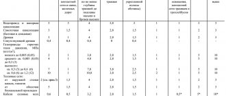
Hot water supply
| 1 Hot water pipeline for heating and ventilation (including air conditioning), as well as general for heating, ventilation, hot water supply and technological processes: | |
| - server | T1 |
| - reverse | T2 |
| 2 Hot water pipe for hot water supply: | |
| - server | T3 |
| - circulation | T4 |
| 3 Hot water pipeline for technological processes: | |
| - server | T5 |
| - reverse | T6 |
Additional signs and explanations
With the help of topographical surveys, all the nuances of the area are displayed on paper: from natural caves to completely man-made gas stations, so to complete the picture, graphic elements are combined with letter ones. Decoding a topographic survey is considered objective only if all the elements “signs plus letters” are taken into account. Some elements, such as the designation of wells on a topographic survey, can be presented in several versions.
Letter symbols on topographic surveys often give schematic images a new meaning, for example, an ordinary rectangle will simply indicate non-scale residential buildings - only complete with letter explanations does the map make sense. So, the designation on the topographic survey TP inside this rectangle will mean that the building is a transformer substation.
Construction should begin with drawing up a drawing
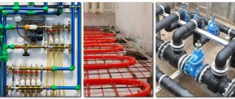
For the most part, modern buildings are equipped with systems that are responsible for meeting sanitary standards. As a rule, this is a whole complex of engineering communications, which includes a hot and cold water supply system, sewerage, gas supply, garbage chute, drains, and heating.
This is necessary for people to live comfortably in a residential building. But in order for all systems to work correctly, the risks of problems must be minimized. And so that in case of any breakdowns the problem can be immediately eliminated, everything is carefully planned. The most important systems, including sewerage and water supply, must be thought out with the highest possible quality, drawn up, and then executed in accordance with a pre-drawn plan. Only if the drawing is drawn up correctly and all its requirements are met, it is possible to build a building that will meet all standards of livability and comfort.
Graphic elements
Conventional graphic symbols on topographic surveys are used to reflect various phenomena and objects on the ground.
To people far from geodesy and cartography, many symbols on topographic surveys will seem like a meaningless set of geometric figures. This should include symbols and a coordinate grid.
Two types of coordinates are accepted on topographic plans or maps:
Coordinates give specialists information about the exact distance between objects.
Tank
A hydraulic tank is an important element that stores hydraulic fluid. A tank connected to the atmosphere is shown on the hydraulic diagram as follows.
A closed tank, or container, such as a hydraulic accumulator, is shown as a closed loop. In mechanical engineering hydraulics, load, spring and gas accumulators are used.
Design work
The general scheme of a sewerage system is an assembly of pipelines connected to plumbing on one side and to treatment facilities on the other. However, for the installation of a specific section of a drainage system, a detailed and accurate drawing is required. When calculating the project, it is necessary to ensure the requirements of SNiP, as well as sanitary standards for the placement of elements. Basic requirements for a drainage project:
- sufficient capacity with some reserve in case of extreme discharge of wastewater;
- correctly calculated configuration, maintained pipe slope;
- the route should be as straight as possible, without sharp turns;
- in the direction of flow of drains, pipes of smaller diameter should be connected to pipes of larger size, and not vice versa;
- the route must be equipped with the required number of inspection wells or inspection elements.
The scheme of the sewerage system is drawn up taking into account its size, purpose and specific use. The compiler’s task includes competent tracing, excluding sudden changes in the direction of the line. In addition, it is necessary to provide for the technologically correct arrangement of pipes and the appropriate position of the plumbing outlet elements. In the process of creating a project, an axonometric diagram of the sewerage system of a residential building is often used. It gives an idea of the spatial position of elements and pipelines. For complex structures with a multilayer structure, this version of the drawing is much more convenient and clearer.
Download a guide to constructing axonometric diagrams
Here it is necessary to focus attention, if one fixture overlaps another in the drawing, and this happens very often, it is necessary to show a dotted line, thereby moving the plumbing fixture away for better visibility.
The axonometry on the diagram should include displays of all pipe diameters. If there is no toilet on the outlet, then the diameter should be 50 millimeters; if there is one, the minimum diameter should be 100 millimeters. All this must be remembered. In most cases, the diameter of the riser is 100 millimeters. Slopes are accepted, also very simply, with a diameter of 100, it is equal to 0.02, and at 50, it should be set to 0.03.
All elements have been applied, now it’s worth taking care of applying the outlets, nothing complicated here either, the diameters should be larger than in the risers, the slope is assumed to be 0.02.
The final touch in drawing axonometry is making marks; here you need to look at the depth of freezing, the location of the foundation, and other factors affecting the marks.
What is an axonometric diagram
The concept of axonometry or axonometric projection means a method of reflecting a three-dimensional figure on one plane, showing three coordinate axes x, y, z on it.
To visualize axonometry, imagine that you are holding a cube figurine made of wire. Now bring the cube to the mirror and trace the faces of the cube reflected in the mirror. On the mirror there will be an axonometry of the volumetric figure of a cube. Here is a visual picture of the axonometry.
In technical drawing, it is customary to make axonometry of figures (parts, products) located at a certain angle to the projection surface.
To simplify calculations, according to GOST 3453-59, build:
- Isometric projections: the angle between the axes is the same (120° each), the dimensions of the figure are distorted equally, the distortion coefficient is 0.82;
- Dimetric: Only two angles between the axes are the same, which means two sizes are the same, the third size is different. The angle between the z and x axes is 97°10′, the angles between the x and y axes, and between the z and y axes are 131°25′.
- Frontal dimetric: the angle between the z and x axes is assumed to be 90°, the angles between x and y and between the z and y axes are assumed to be 135°.
- In all axonometric options, the z axis is located vertically.