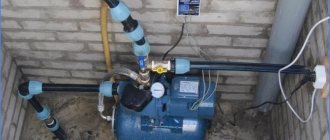
In some cities, due to the unsatisfactory condition of the central water main, pumping station, etc., water is supplied to private houses and apartments on schedule. Therefore, residents strive to store water in small containers - plastic bottles, buckets, etc. If they have the money to avoid this inconvenient method of accumulating water, many owners try to install a storage tank with a pumping station at home.
Water supply system for a private house with a storage tank - photo.
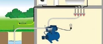
A water supply system with a storage tank will help for a short time (1 - 5 days), if it is not replenished, it does without a central water supply, and in cases of unsatisfactory pressure, increase it.
Let's consider one of the practical water supply schemes for a house (apartment) with a storage tank and a pump for the existing pipework.
Scheme of water supply for a house with a storage tank
The presented scheme can be easily integrated into existing piping, both in water supply with one central pipeline and with several. Its compactness is due to the use of free space above the tank, in which the pumping station is suspended on brackets.
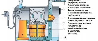
Picture 1.
Figure 1 shows a water supply diagram for a private house with two central pipelines consisting of:
- 1 - tank 500 liters;
- 2 - pump;
- 3 — receiver (membrane tank);
- 4 - pressure switch;
- 5 — bronze five-point adapter;
- 6, 17 — pressure gauge;
- 7 — hose with reinforcing braid;
- 8 - check valve;
- 9 — float valve;
- 10 - American with external thread;
- 11 — American with internal thread;
- 12 - bronze transition from the container to the external thread;
- 13, 14 — MRN (male thread coupling);
- 15 — МРВ (internal thread coupling);
- 16 - bronze transition from external thread to internal thread;
- 18 — flow meter;
- 19 — mesh filter;
- 20 - 26 shut-off valves.
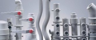
The suction discharge and distribution line is made of polypropylene pipeline and transitions with diameters of 32 mm (suction) and 20 mm.
Price
The price level for storage tanks for water supply depends on their volume and material of manufacture.
A model with a volume of 200 liters, made of food-grade plastic, costs around 4,000 rubles.
A larger tank, for example, 700 liters, will cost the consumer approximately 8,000 rubles.
Containers made of stainless steel are much more expensive:
- volume 180 liters – 13,700 rubles;
- 635 liters – 30,500 rubles.
However, despite this difference in price, the majority of consumers prefer steel storage tanks.
The distribution of water pipes in a private house is installed after all construction work has been completed. Water distribution in a private house - external and internal distribution, installation of the system.
You can familiarize yourself with sanitary standards and requirements for organizing protective and security zones of water intake sources in this article.
How the system works
When drawing water from the central main, shut-off valves 23, 24 must be closed, and valves 20, 21, 22, 25 must be in the open position, and the voltage to the pumping station must be cut off by an automatic switch. Water flows through the primary filter and float valve into the tank. When a certain level is reached, the valve closes, and to prevent leakage that may occur if the valve is broken or clogged, the water supply is shut off by valve 25.
When the water supply to the house is stopped, shut-off valves 20, 21, 22, 25 are closed and taps 23, 24 are opened, and electrical power to the pump is restored.
When the mixer is opened, water flows from the receiver, and when the pressure drops to the lower limit (1.8 bar), the automation unit turns on the pump, which supplies liquid from the reservoir to the pipeline and membrane tank. The pressure switch will turn off the pump when the pressure in the discharge system reaches 2.8 bar. Liquid consumption is a cyclical process, and the appearance of water in the city energy network will be signaled by pressure gauge 17.
We will consider in detail the important components of the storage device to determine the installation method and criteria for selecting equipment.
Design
Storage tanks for water supply are made of food-grade stainless steel (steel grade - 12Х18Н10Т) or food-grade plastic.
The material must be of high quality, otherwise unwanted chemical compounds will get into the water, which is harmful to the health of people consuming this water.
Design Features:
- A float valve of the kind used in toilet tanks is installed on the inlet pipe. If water is pumped into the tank from your own well or well, a float switch for the pump is installed instead of a tap.
- In case of failure of the float mechanism, an overflow pipe connected to the sewer is cut below the inlet.
- It is also necessary to install a filter at the entrance. There are several varieties: mesh (mud collectors), cyclones and centrifugal filter pumps. The first group is used for relatively clean water, the other two – for highly polluted water. A strainer should also be installed on the outlet pipe. It is better if it is located at the entrance of the main pipe into the house immediately before the wiring.
- A level is inserted into a tank with opaque walls. It will help determine whether there is enough water, for example, for a washing machine.
- It is necessary to ensure that sediment can be removed. Underground containers, as already mentioned, are cleaned through a hatch located on top. Tanks intended for installation at the top are equipped with a drainage pipe that cuts into the very bottom.
- Filling the tank should be done through a diffuser - a shower head or garden watering can. This will prevent water from mixing with the bottom layer containing sediment.
- A ventilation pipe (blowhole) cuts into the container from above. It should be curved so that the inlet is directed downward. A mesh should be installed at the entrance to the ventilation pipe to prevent debris and insects from entering the tank.
The ventilation pipe must have a sufficiently large diameter. It is also necessary to ensure that its filter is not clogged with all kinds of debris, for example, poplar fluff. If you drain a tank without air, atmospheric pressure can flatten it like a tin can.
Electrical part
The station motor is powered directly from the electric meter through a circuit breaker.
To protect the pump, quickly de-energize the engine in cases of unstable power supply or rotor overload, it is advisable to select a machine 10% more than the rated power. For the station motor used in the example, the rated power is 0.77 kW, taking into account the requirements, you need to use a 3.85 A circuit breaker ((770 W + 77 W) / 220 V), but the closest parameter is 5 A. You can use a circuit breaker with differential control.
As practice shows, conventional circuit breakers with similar current parameters cope with their functions quite well.
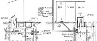
Possible pipe routing options
The house's water supply scheme is designed with two central pipelines. Usually they are installed at a distant distance from each other. In this case, one pipe is mounted close to the system, and the second is installed in the corner between the wall and the ceiling, or in the floor screed. When choosing option 1, communications can be covered with a decorative box made of gypsum plasterboard (plasterboard sheet). In the second case, a groove is made in the screed, preferably near the wall, a pipe is laid out with permanent fittings, a protective casing is installed on it and the entire line is hidden under a cement-sand mortar.
Tank and pumping station
A plastic cylindrical tank with a volume of 0.5 m3, a cross-section of 640 mm and a height of 1840 mm, with a wall thickness of 5 mm, is used as a storage tank.
The pumping station consists of:
- JEX 500 pump with low noise emissions, capable of providing system pressure up to 4 bar. When using a noisy unit in an apartment, conflicts with neighbors may arise, even leading to litigation.
- Receiver 24 liters. Significantly reduces water hammer on the pump that occurs during water extraction, and also increases engine life.
- A special bronze five-terminal adapter, with the help of which all components of the station are switched.
- Tubes with reinforcing braiding designed to connect the pump and the membrane tank.
- An automatic unit (pressure switch) for operating the pump in a certain pressure range.
- Pressure gauge. This device is not a mandatory attribute for the station, but based on its readings, you can check the tightness of the circuit and, if necessary, configure the automation unit.
Pumping station.
The ceiling height in the room where the described water supply system is installed is 2.5 m. This distance allows you to install a station with dimensions of 600 X 400 X 400 above the storage tank. To attach it, brackets from air conditioners are used, and a rubber hose with a diameter of 32 mm and a length of 400 mm, cut lengthwise, is used as a vibration pad.
Water supply to the tank
The container is filled through a plunger-type float valve, consisting of:
- branch pipe with housing and outlet;
- plunger with rubber seal;
- lever;
- float
A valve of this design is reliable in operation, but sometimes it can fail due to foreign objects getting into the drain hole or working space of the plunger, or wear of the rubber seal. It is advisable to periodically monitor its operation, and after filling the container, the flow of liquid is additionally stopped by valve 25.
Launching a water supply system for a private home
A prerequisite for the system to operate before the first start of the pump, in cases where the reservoir is completely empty, is the presence of water in the turbine chamber and suction line. If this requirement is not met, the liquid will not flow to the disassembly point, and the pump elements will overheat and fail.
Procedure for filling the suction line.
Step 1
A plug is unscrewed from the upper part of the turbine housing, and a watering can is inserted in its place (photo 7).
Step 2
A dry cloth is placed under the body to catch liquid during the filling process.
Step 3
Water from a plastic bottle, in small portions, is fed into the suction line until it flows out from under the watering can.
Step 4
The watering can is removed and a plug is installed.
After the above activities, the station is ready for launch.
The suction can be filled in a reverse way, that is, if there is water in the main pipeline, to avoid water hammer on the blades, smoothly open valve 23 or 24 and do not close it until the readings appear on pressure gauge 6.
Device
As we have already said, our device is divided into two parts by a pear. One of them collects liquid, the other collects compressed air. After filling the bulb, the water pressure will be balanced by air pressure, so the capsule liquid will not touch the metal walls of the tank. The membrane does not inflate to significant sizes through internal air pressure. A valve is installed on the body to regulate pressure.
Note! The supply pipes must be connected to the hydraulic accumulator in such a way that the device can be quickly disassembled for repairs without draining the water from the system.
In tanks with a volume of more than 100 liters, a special valve is provided, which serves to remove excess air released from the liquid. In smaller containers, a special tap is used for such purposes.
Emergency overflow and drain
To protect against flooding of the room in cases of overfilling of the container, an emergency overflow is installed in its upper part, consisting of:
- transition with a diameter of 1 inch;
- corrugated hose with a cross section of 32 mm;
- siphon for washing;
- fastenings for sewer pipe 50 mm.
A tee with a 45-degree outlet was installed into the existing sewer system. The outlet pipe of the siphon is connected to the tee through a rubber transition from a diameter of 32 mm to a cross-section of 50 mm. For reliability, these components are treated with silicone sealant.
When it is not possible to supply liquid by the pump (breakdown, no electrical power), the water is drained through an emergency drain located in front of the suction line check valve.
In this case, the drain valve 26 is placed as close to the bottom as possible.
Types
The storage tank can be a container with sufficient internal volume, made of a material that is resistant to corrosion and safe for storing drinking water. The following materials are used:
- polyvinyl chloride;
- cross-linked high or low pressure polyethylene;
- polypropylene;
- stainless steel;
- steel coated with waterproof varnishes and ceramic coatings.
Plastic Tanks
Although galvanized steel is corrosion-resistant and waterproof, over time the protective layer of zinc can wear thin, especially at joints and welds.
By design there are:
- open containers that have a neck with or without a lid, but with sealed walls and bottom;
- closed, completely sealed membrane-type containers.
In the first case, everything is simple: the entire internal volume is filled with water and, if necessary, drained through a pipe fixed at the lowest point.
In the case of membrane storage tanks, the useful volume is at least a third less than the volume of the entire structure. Part of the volume is allocated under the air chamber, separated from the water using a durable elastic membrane. As the container fills with water, the membrane presses on the air chamber, creating excess pressure. When it is necessary to get water back, the valve opens and it enters the water supply system under the influence of accumulated pressure.
Leak search
The device is not sealed due to:
- wear of the sealing gasket of the toilet tank;
- damage to the rubber or ceramic seal of the mixer, shut-off valves;
- the presence of cracks in the membrane or a malfunction in the spool-type valve of the receiver;
- use of defective components;
- violations of assembly technology.
Signs of a leak in the system:
- there is no water extraction, and the pump turns on periodically;
- when the device is de-energized, the station pressure gauge shows a decrease in pressure down to 0 bar.
If the above symptoms appear in the wiring, you must:
- Disconnect power to the pumping station.
- Close valves 23, 24.
- Monitor the readings of pressure gauge 6; if they change, it means that the leak is in the fittings of the pump, the suction line, the discharge pipeline to the specified valves, or in the receiver.
- If the pressure is unchanged, open the supply valve (23 or 24) and monitor the pressure gauge values. If a leak is detected, we examine the system components from the shut-off valves to the last element of the water supply system. We check the second tap using the same system. Any identified leaking components must be reviewed or replaced. In the place where the pipes are located (if they are hidden in the screed), it is difficult to determine the leak, since, usually, materials are laid on the floor that repel or poorly absorb water: tiles, linoleum, laminate, etc. Therefore, in such places when installing a water supply system In a private house, it is better to lay solid pipes and avoid joints.
Criterias of choice
When determining the required volume of the tank, the number of residents of the house and the number of water intakes that are capable of simultaneous consumption of liquid from the tank are taken into account. For example, a 20-30 liter battery can meet the needs of a family of 3-4 people. The productivity of pumping equipment should be approximately two cubic meters per hour.
The larger the volume of the hydraulic tank and the lower the water consumption, the less often the automation starts the pumping equipment. More than six starts per minute will result in a 20 percent increase in supercharger wear. When running more than ten times per minute, the wear rate increases by 30–40 percent. Also, small tanks offer almost no protection against water hammer.
Hydraulic tanks can be installed in two positions: horizontal or vertical. If space allows, purchase the first option. If there is a shortage of space, a vertical device is chosen.
Pay attention to the material of manufacture. Steel tanks are more reliable because plastic is prone to deformation. The presence of a membrane protects the metal walls from corrosion. But steel structures are more difficult to install due to their significant mass.
Setting up the automation unit
The automation unit consists of a membrane with a working element, a contact group, a housing, and adjusting screws.
Under the influence of pressure, the rubber membrane expands or contracts, while its working element switches the contacts from the “On” position. to the "Off" position At the factory, the pressure switch is set to maintain a pressure of 1.8 - 2.8 bar, that is, when 1.8 bar is reached, the pump turns on, and when 2.8 bar it turns off. A timely inspection of the automation, which consists of cleaning the inlet (connecting port) and the contact surface, allows it to operate smoothly without adjustment. But since the relay contains adjusting devices, let’s consider how the unit can be switched to a different operating range.
Pressure switch.
If you turn the No. 1 stud nut clockwise, the upper response range will increase; if you turn it counterclockwise, this range will decrease. Nut No. 2 adjusts the lower response limit. To quickly achieve the best results, after small changes you should check the results of the adjustment. The device is very sensitive and every setting, even one that is not significant at first glance, leads to a change in the response limit of the device.