APPENDIX A
(recommended)
Approximate list of as-built diagrams for elements, structures and parts of buildings and structures, landscaping and geodetic alignment basis
1. As-built diagram of the geodetic alignment base at the construction site.
2. As-built diagram of the location (layout) of the main axes of the building (structure).
3. Executive diagram of the pit.
4. High-altitude as-built diagram of piles after their immersion (driving).
5. As-built diagram of the pile field (after cutting down the piles).
6. As-built diagram of grillages.
7. Executive diagram of foundations.
8. As-built diagram of foundations for equipment and their elements (anchor bolts, embedded parts, technological holes, wells, etc.).
9. Tiered executive diagrams of columns of frame buildings.
10. Executive diagram of the roof.
11. Executive diagram of crane beams and tracks.
12. High-rise as-built diagram of the support areas for panels, floors and roofing of the building.
13. High-rise design diagram of the floors of an industrial building.
14. Executive diagram of the elevator shaft.
15. Floor plans for multi-storey buildings.
16. High-rise design diagram of column consoles.
17. As-built diagram of the territory after completion of the improvement work.
18. As-built diagram of the roadbed of a transport structure (road or railway, internal road, overpass and other engineering structures).
19. Executive diagrams of tanks, cooling towers, masts, chimneys and other engineering structures.
Engineering systems drawings
The development of plans for utility networks is carried out on the basis of working drawings of the general plan, roads and railways or topographic plans.
The following designations are applied to the plans of engineering systems:
- already constructed and designed buildings and utilities that affect the construction and installation of networks;
- coordinates of engineering systems and their binding to the coordinates of structures;
- diameters of the designed pipeline systems;
- wells, chambers, storm water inlets, crossings under road and railway tracks.
Trunk system plans may contain picket numbers (PK) with reference to network sections. At the customer's request, it is possible instead of plans by engineer. systems execution of individual fragments. In this case, the names of the plans are indicated without abbreviations.
APPENDIX B
(required)
Requirements for the content of the as-built drawing and longitudinal profile of the underground network
B.1 Requirements for the content of the as-built drawing
B.1.1 The as-built drawing must include the geometric parameters of the following characteristic points and lines of the laid utility network, including its overhead sections, as well as existing networks exposed during construction:
well centers, well hatches and chambers;
network turning points, main points of curves (beginning, middle and end) during smooth turns in plan, break points and bends in height;
centers of transition places from underground to aboveground;
points of intersection of the axis of the main network with the axis of connection or tap;
the alignment points of the axis (top of the laying) on straight layings at least every 50 m (in undeveloped areas with a long distance, it is allowed to place alignment points every 100 m);
points of intersection of the axes of inputs and outputs with the outer edges of buildings (structures);
axes of existing networks intersecting or running parallel to the laid one, opened during construction;
end, turning and turning points on cases (casings);
places where the diameter and material of pipes change;
location of disconnecting devices located outside chambers and wells.
B.1.2 For certain types of networks, the as-built drawing, in addition to the points specified in B.1.1, must include the geometric parameters of the locations of the following elements and devices and provide additional information:
for water supply systems and pipelines for special technical purposes (product pipelines) - supports for overhead installation, fire hydrants, valves, plungers, emergency outlets, standpipes, stops at turning angles, plugs, dimensions of wells and chambers;
for sewerage and drainage - emergency outlets, heads of drainage outlets, storm inlets, storm drains, treatment facilities on drains, stops at the angles of rotation of pressure sewers, dimensions of chambers, buildings of pumping stations and pumping stations;
for underground drainages - type of drainage, material and cross-section of trays and trenches for closed drains, material and cross-section of a blind collector;
for heating networks - supports for overhead installation, compensators, valves, fixed supports, dimensions of chambers, above-ground pavilions above the chambers and buildings of central heating points, type of installation and channel, as well as all data on associated drainage, drainage from the channel and all utility networks located in the channel;
along gas pipelines - carpets, pressure regulators, valves, hydraulic valves, control pipes, condensation pots, plugs, dimensions of gas distribution points and stations;
for electrical cables - linear and tee couplings, cable reserve loops, transfers, exit points to supports and walls of buildings, dimensions of distribution points, transformers and traction substations;
for electrical protection structures against corrosion - contact devices, anode grounding conductors, electrical protective installations, electrical jumpers, protective grounding and drainage cables;
for telephone sewerage - the total number of channels on each span, the sizes of non-standard wells and chambers, places of exits to buildings and telephone distribution cabinets.
B.1.3 If the as-built documentation does not contain a longitudinal profile, the following marks are also given: the shell of the inspection hatch and the bottom of the well; the bottom of the gravity tray and the top of the pressure pipeline; tops of pipes, armored cables and cable duct packages at critical points; the surface of the earth (trench edges) near wells and at target points.
B.1.4 The as-built drawing must contain data on: the purpose of the network; quantity, material and diameter of pipes; number of voltages and cable brand; gas pressure.
B.1.5 On the as-built drawing or a separate sheet attached to it, in the scale adopted in the project, the following are depicted:
plans and sections of wells or their type is indicated;
all characteristic sections of collectors, channels, cases, cable duct blocks, cable packages;
development of cable wells;
other details of the network and structures on it, indicating the required linear dimensions characterizing the constructed structure;
symbols of the utility networks shown on this sheet.
The as-built drawing of the laid water pipeline or the separate sheet attached to it, in addition, depicts an out-of-scale general diagram of the laid network, indicating the external dimensions of the structures, the diameters and material of the pipes, the length of individual sections of the network, stops at the angles of rotation, valves, disconnected sections of existing networks.
B.2 Requirements for the content of the longitudinal profile
B.2.1 The following must be marked on the longitudinal profile: the laid utility network, including its above-ground sections; existing underground networks exposed during construction; existing underground networks located below the laid one (drawn according to the topographic plans used for the development of the project).
B.2.2 The longitudinal profile indicates: design and actual elevations of the ground surface and elements of the laid network, specified in B.1.1 and B.1.2; horizontal distances between leveling points (chainage, numbering); magnitude and direction of slopes; number of cables or pipes; pipe diameters; characteristics of road pavement structures and their foundations exposed during construction.
Sketch drawings of non-standard products
The execution of sketch drawings developed for elements of engineering structures that are not mass-produced is regulated by GOCT 21.114. Separate sketch drawings are created for each element with non-standard parameters. It is allowed to create group drawings for components of a structure that have common design features. Sketch drawings are assigned independent designations, which include the name of the set of RF (working drawings) in accordance with GOST 21.101, code H and the serial number of the sketch drawing.
Example:
- 2З45-11-HBK.H1/
APPENDIX B
(required)
Shape, dimensions and filling of the main inscription of documentation for underground networks
[IMAGE]
Field 1 indicates the name of the construction organization that installed the network.
Field 2 indicates the name of the customer organization (developer).
Field 3 indicates the name of the design organization.
Field 4 indicates the number, code and release date of the project.
Field 5 contains information about the approval of the project
Field 6 indicates the name of the as-built drawing and underground installation, the address of the facility and the length of the route.
Field 7 indicates the number and date of issue of the permit to carry out construction and installation work.
Fields 8 - 11 indicate the positions, surnames, signatures of the performers and responsible managers of the work, the dates of signing the drawing, and also, if necessary, the name of the third-party organization that compiled the as-built drawing.
General information on PD
The technical documentation package additionally includes situational plans for engineering systems, basic parameters of water supply and sewerage systems, engineering-geological characteristics, special requirements for systems regarding explosion safety, soil chemical activity, as well as additional requirements.
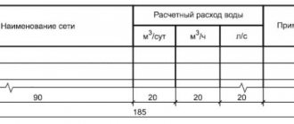
The main indicators of engineering networks are indicated in a table made according to Form 1.
Preface
Preface
The goals, basic principles and basic procedure for carrying out work on interstate standardization are established by GOST 1.0-92 “Interstate standardization system. Basic provisions" and GOST 1.2-2009 "Interstate standardization system. Interstate standards, rules and recommendations for interstate standardization. Rules for the development, adoption, application, updating and Center for the methodology of regulation and standardization in construction" (JSC "CNS")
2 INTRODUCED by the Technical Committee TC 465 “Construction”
3 ADOPTED by the Interstate Scientific and Technical Commission for Standardization, Technical Regulation and Conformity Assessment in Construction (MNTKS) (Minutes dated December 8, 2011 N 39)
The following voted for adoption:
| Short name of the country according to MK (ISO 3166) 004-97 | Country code according to MK (ISO 3166) 004-97 | Abbreviated name of the national construction management body |
| Azerbaijan | AZ | Gosstroy |
| Armenia | A.M. | Ministry of Urban Development |
| Kazakhstan | KZ | Agency for Construction and Housing and Communal Services |
| Kyrgyzstan | KG | Gosstroy |
| Moldova | M.D. | Ministry of Construction and Regional Development |
| Russian Federation | RU | Department of Architecture, Construction and Urban Development Policy of the Ministry of Regional Development |
| Tajikistan | T.J. | Agency for Construction and Architecture under the Government |
| Uzbekistan | UZ | Gosarchitectstroy |
| Ukraine | U.A. | Ministry of Regional Development, Construction and Housing and Communal Services |
4 By Order of the Federal Agency for Technical Regulation and Metrology dated October 11, 2012 N 484-st, the interstate standard GOST 21.704-2011 was put into effect as a national standard of the Russian Federation on May 1, 2013.
5 INSTEAD GOST 21.604-82
Information on the entry into force (termination) of this standard is published in the monthly published information index “National Standards”.
Information about changes to this standard is published in the annually published information index “National Standards”, and the text of changes and amendments is published in the monthly published information index “National Standards”. In case of revision or cancellation of this standard, the relevant information will be published in the monthly published information index “National Standards”
AMENDED Change No. 1, approved and put into effect by Order of the Federal Agency for Technical Regulation and Metrology dated November 25, 2016 N 1801-st from 07/01/2017
Change No. 1 was made by the database manufacturer according to the text of IMS No. 3, 2021
Specifications for equipment, elements and materials
Specifications for HBK are drawn up in accordance with GOST 21.110. Specifications are compiled in sections: HK and HB. Elements of engineering systems in sections are recorded for each system in groups. The parameters are indicated:
- equipment;
- elements of structures;
- pipeline fittings (regulating, shut-off, protective);
- embedded elements;
- pipe products;
- thermal insulation structures;
- materials.
Tubular products are recorded for each diameter size. Parameters of equipment, materials and elements are recorded in ascending order. When drawing up specifications, parameters may not be specified.
The specifications do not include parameters of certain types of products - bends, crosses, reducers, flanges, gaskets, fasteners (flanges, bolts, nuts, washers). The standard sizes of such products are determined by the customer based on the requirements for the designed structures.
Units of measurement indicated in the specification:
- equipment and metal products are indicated in pieces (pcs);
- linear meters (m) are used to indicate the number of tubular products;
- pipeline elements (fittings and fittings) are indicated in pieces (pcs);
- the amount of thermal insulation materials is calculated in cubic meters (m3);
- volumes of protective materials and coatings are indicated in square meters (m2);
- kilograms (kg) or tons (t) are used to indicate quantities of other materials.
Specifications for equipment, components and materials are drawn up separately. Such a document is assigned a designation that consists of the name of the RF kit and the CO code. Examples of notation:
- 1 2З45-11-HBK.CO;
- 2 2З45-12-HB.CO.