What is a project called?
A project is a package of documents that are prepared during the design of newly constructed engineering structures and structures. The set of documents consists of estimates, specifications for materials and components, plans, drawings, diagrams, explanatory notes. External networks are laid according to standard and individual projects. When designing components of pipeline systems, as a rule, standard design solutions are used, which have been repeatedly tested in practice.
Working documentation is a set of documents that contains detailed information about the engineering structure under construction. Detailed solutions of designers contain a sufficient amount of information to provide the facility with the necessary amount of equipment, materials and components.
Dividing project documentation into two parts (design and working) allows you to speed up the process of obtaining permission to construct pipeline networks. To obtain permission to carry out construction and installation work, sufficient design documentation is required. After the project passed the state. examination and corrected all comments and shortcomings, they begin to work on working issues.
PD consists of:
- working drawings, which are used as the basis for construction and installation work;
- specifications for equipment and materials according to GOCT 21.110;
- local estimate.
The main set of working drawings of the HBK brand includes two sets - working drawings HB (external water supply networks) and HK (external sewerage networks).
Documentation package PD, consisting of HB, HK, HBK, which includes general information on working drawings, plans, profiles and network elements, pressure network diagrams. Designations and marking of networks are carried out in accordance with GOCT 21.205. For example - B2, K2. For pressure sections of networks, the index H is added to the marking. For example, K4H. Network elements are designated by brands and serial numbers within each network.
Table 1.
| Component name | Marking |
| Wells or chambers with fire hydrants | PG |
| Storm water inlets | D |
| Break points connected without wells | T |
| Rotating angles | UP |
| Fixed supports (for above-ground pipelines) | N |
Wells and chambers not listed in Table 1 are designated by serial numbers without marks. The numbering of network components starts from the boundaries of the structure or water supply source. The outlets of sewer networks in the drawings are designated by the words “Outlet” or “Outlet K1”.
The length of the pipeline system, the gap between wells, turning angles and break points are indicated in meters to hundredths of a decimal point. The diameter of the pipe and the thickness of its wall are indicated in mm. The bend of the turning angles is indicated in degrees.
On plans and drawings, pipeline networks are indicated using conventional graphic elements in accordance with GOST 21.205 and GOST 21.206. Visible areas are indicated with a solid thick line, invisible areas with a dashed line. Buildings, structures and utility networks for other purposes, already built or designed, which have an impact on objects under construction, are indicated using a solid thin line.
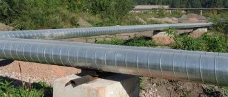
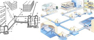
Figure 1. Example of graphical image. pipeline systems.
The nominal diameter or nominal diameter (DN) is given with the index DN and the sign Ø, after the index x the wall thickness is indicated.
Figure 2. Example of a graphical representation of piping systems.
The designation of soil types and their characteristics, including acidity, consistency, degree of moisture is carried out according to GOCT 21.302. Graphic images are indicated in the drawings on the scale indicated in Table 2.
Table 2.
| Images | Scale |
| Situational plan engineering set. | not standardized |
| Utility plans | 1k500; 1k1000; 1k2000; 1k5000 |
| Knots engineering set | 1k20; 1k50 |
| Profiles engineering set. | |
| - horizontal | 1k200; 1k500; 1k1000; 1k2000; 1k5000 |
| - vertical | 1k100; 1k200; 1k500 |
| Schemes of pressure engineering networks | not standardized |
| Cuts and knots | 1d10; 1k20; 1d50; 1k100 |
| Sketch drawings of non-standard products | 1d5; 1d10; 1k20; 1d50; 1k100 |
If necessary, the plan is divided into several sections, which are located on separate sheets. The plan section is assigned a designation indicating, for example, its connection to pickets.
Marking example:
- Plan PK0-PL50+10.00.
- Profile B2 PK0-PK75+40.00.
WATER INJECTIONS
10. Water intake According to GOST 19185-73 11. Water intake structure According to GOST 19185-73 12. Water intake mine well A well with fixed walls for collecting groundwater through the bottom and walls 13. Water intake well A well for collecting groundwater, usually equipped with casing pipes and a filter 14. Radial water intake structure A water intake structure for groundwater, consisting of horizontal or inclined water receiving radial beam filters 15. Water collection well A well for collecting water from other water intake structures 16. Water intake shaft filter A device that prevents the removal of particles into the mine well soil together with water from the aquifer 17. Infiltration structure A structure for the intake of groundwater or its artificial replenishmentGeneral information on PD
The technical documentation package additionally includes situational plans for engineering systems, basic parameters of water supply and sewerage systems, engineering-geological characteristics, special requirements for systems regarding explosion safety, soil chemical activity, as well as additional requirements.
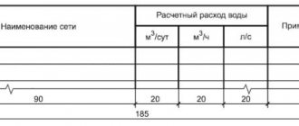
The main indicators of engineering networks are indicated in a table made according to Form 1.
GENERAL CONCEPTS
GENERAL CONCEPTS
1. Water supply According to GOST 19185-73 2. Water supply A complex of structures including a water intake, water pumping stations, a water purification or water treatment station, a water supply network and reservoirs for providing water of a certain quality to consumers 3. Group water supply A water supply system supplying water to consumers of several settlementsEngineering systems drawings
The development of plans for utility networks is carried out on the basis of working drawings of the general plan, roads and railways or topographic plans.
The following designations are applied to the plans of engineering systems:
- already constructed and designed buildings and utilities that affect the construction and installation of networks;
- coordinates of engineering systems and their binding to the coordinates of structures;
- diameters of the designed pipeline systems;
- wells, chambers, storm water inlets, crossings under road and railway tracks.
Trunk system plans may contain picket numbers (PK) with reference to network sections. At the customer's request, it is possible instead of plans by engineer. systems execution of individual fragments. In this case, the names of the plans are indicated without abbreviations.
A few words about drainage systems
It is not recommended to discharge surface and domestic wastewater into the same sewer network. If the site requires drainage, for example, is located in lowlands or in areas with poorly draining soils, the drainage system must be equipped separately.
Local treatment facilities "LOS"
There are different drainage systems:
- Storm drainage.
- Wall drainage.
- Deep drainage.
Stormwater includes gutters and storm water inlets. It collects rainwater, preventing its negative impact on the foundation of the house. Wall drainage also serves the same purpose - protecting the foundation.
The most difficult type to install are deep drainage systems. To lay such a drainage system, special perforated pipes are used. Through holes in their walls, groundwater enters the drainage system, from which it is discharged to the discharge point. You should not connect drains to a septic tank that collects household wastewater. When the groundwater level rises sharply, for example, during melting snow or heavy rainfall, the load on the septic tank increases significantly. As a result, he ceases to cope with his tasks.
Longitudinal profiles of networks
The image of longitudinal profiles is performed in the form of a scan along the axes of pipeline systems. Above the profiles, above-ground structures and the depth of utility lines are indicated. Data on:
- the surface of the earth and the level of soil water;
- existing or planned roads, railways and tramways that intersect with utility networks;
- cases for pipeline systems indicating geometric parameters.
Pipeline systems are depicted with 2 lines if their diameters on the indicated scale are equal to two millimeters. The above data is presented in a side table, which looks like this:
Form 2.
For laying utilities overhead, the side of the table will look like this.
Form 3.
At the customer's request, the table can be supplemented with data, for example, information about pickets and the height of supporting structures, a diagram of engineering. networks, soil characteristics - its subsidence, acidity, swelling.
Schemes of pressure engineering networks
Pressure systems are indicated in plan without scale. Provides information about:
- pipeline networks, indicating the length of their individual sections, parameters of fittings, shut-off and control valves, stops, fixed support structures and other parts of the structure;
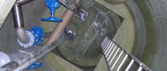
- service wells with the pipeline axes tied to the surfaces of its internal walls;
- secant planes of transverse sections and their designations;
- positional designations of structural elements.
Diagrams of pressure systems contain graphic images of pipeline systems, their elements, control and protective fittings, as well as chambers, service wells for other structures and structures. At the customer's request, images of sections, nodes or other types of structural elements are applied to sheets with diagrams. Diagrams of pressure engineering systems with overhead installation show the breakdown, alignment and types of all supporting structures with the designation of the distances between them.
The names of pressure system diagrams indicate their designations in full, for example:
- Network diagrams B2, K4H.
Installation features
Installation of external sewerage begins with excavation work. A pit is being dug for installing a septic tank or VOC, and trenches for laying a pipeline. The external non-pressure sewerage pipeline is installed maintaining a slope of 2° per linear meter of pipe. The trench is located below the freezing level of the soil. If it is impossible to lay a pipeline at this level, the pipes must be thermally insulated. The depth of the pipeline depends on the area and is determined by building codes. The width of the trench depends on the diameter of the pipe. For example, with a pipe diameter of 110 mm, the trench must have a width of at least 600 mm.
Before laying pipes, the bottom of the trench must be dry. For this, different methods are used - static lowering of the groundwater level, horizontal or surface drainage. The choice of one option or another depends on the type of soil and the depth of the trench to be drained. A sand cushion is laid out at the bottom. When arranging the cushion, a slope towards the septic tank or wastewater treatment plant must be maintained.
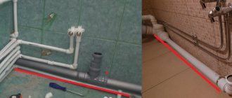
Pipeline laying
Pipeline in trench
The best choice for a sewer pipeline in a suburban area is plastic pipes. In this case, it is necessary to look at the markings, since products for internal sewerage are not suitable for external installation. It is advisable to install the pipeline in such a way as to minimize the number of turns. If necessary, adapters are used.
Turning points, especially if their angle is incorrectly maintained, are the main areas for blockages to occur. To clean the external sewerage pipeline, it is necessary to install inspection wells. The distance between them on straight sections should be at least 13–15 meters. Ready-made plastic products or ordinary reinforced concrete rings are used as inspection wells. If the site requires additional drainage, it is necessary to equip a drainage system.
Experts do not recommend collecting domestic wastewater and surface water in one collector. It is better if both systems are arranged separately.
The pipes are laid at a slope, ensuring gravity movement of liquid from the house to the collector. In order to maintain this slope, you can use a hydraulic level along which the main line is set. If the pipe connecting the internal and external sewers is laid at a large angle, it is advisable to make a small riser that allows you to level the angle of the pipeline. A large slope harms the operation of the sewer network no less than an insufficient slope.
To ensure a high-quality connection of pipe sections, it is necessary to lay them strictly along the same axis. The connection is made using a socket or special shaped elements. To ensure sealing of the joints, as well as to simplify the connection, it is recommended to lubricate the socketless end with Vaseline. The use of oils and technical lubricants for these purposes is strictly prohibited. After laying the pipeline, the trench is backfilled layer by layer. The first layer of soil is thoroughly compacted. This ensures a reduction in pressure on the pipes from the outside. Each layer is spilled with water, which further strengthens the soil.
Sewage system installation diagram
When using VOCs, it is necessary to ensure the removal of treated water. For this purpose, an additional pipeline is laid from pipes with a diameter of 50–110 mm. For forced drainage of water, pipes with a diameter of 25 mm can be used. The length of the pipeline depends on the landscape of the site and the distance from the treatment plant to the discharge site. The optimal distance is 10 meters.
A serious problem with any external utilities is the risk of freezing at low temperatures, especially in areas with harsh climates. Gravity lines leading into a septic tank or sewer are practically not subject to freezing. In order to minimize the risk of pipeline freezing, it is necessary to adhere to a number of rules when laying it:
- The slope must be carefully observed along the entire length of the highway.
- The highway should not sag.
- In areas with low winter temperatures, an additional heating cable can be installed.
When using a heating cable, it is laid in a trench next to the pipe. To protect it, it is better to place it in a plastic pipe with a diameter of 25 mm. It is not recommended to use corrugated pipes for laying heating cables, as the corrugation may collapse over time, which will reduce the protection to zero.
Sketch drawings of non-standard products
The execution of sketch drawings developed for elements of engineering structures that are not mass-produced is regulated by GOCT 21.114. Separate sketch drawings are created for each element with non-standard parameters. It is allowed to create group drawings for components of a structure that have common design features. Sketch drawings are assigned independent designations, which include the name of the set of RF (working drawings) in accordance with GOST 21.101, code H and the serial number of the sketch drawing.
Example:
- 2З45-11-HBK.H1/
Specifications for equipment, elements and materials
Specifications for HBK are drawn up in accordance with GOST 21.110. Specifications are compiled in sections: HK and HB. Elements of engineering systems in sections are recorded for each system in groups. The parameters are indicated:
- equipment;
- elements of structures;
- pipeline fittings (regulating, shut-off, protective);
- embedded elements;
- pipe products;
- thermal insulation structures;
- materials.
Tubular products are recorded for each diameter size. Parameters of equipment, materials and elements are recorded in ascending order. When drawing up specifications, parameters may not be specified.
The specifications do not include parameters of certain types of products - bends, crosses, reducers, flanges, gaskets, fasteners (flanges, bolts, nuts, washers). The standard sizes of such products are determined by the customer based on the requirements for the designed structures.
Units of measurement indicated in the specification:
- equipment and metal products are indicated in pieces (pcs);
- linear meters (m) are used to indicate the number of tubular products;
- pipeline elements (fittings and fittings) are indicated in pieces (pcs);
- the amount of thermal insulation materials is calculated in cubic meters (m3);
- volumes of protective materials and coatings are indicated in square meters (m2);
- kilograms (kg) or tons (t) are used to indicate quantities of other materials.
Specifications for equipment, components and materials are drawn up separately. Such a document is assigned a designation that consists of the name of the RF kit and the CO code. Examples of notation:
- 1 2З45-11-HBK.CO;
- 2 2З45-12-HB.CO.
ALPHABETIC INDEX OF TERMS
| Water aeration | 24 |
| Water tower | 55 |
| Water supply inlet | 49 |
| Water pipeline | 44 |
| Water intake | 10 |
| Water treatment | 19 |
| Water consumption | 5 |
| Specific water consumption | 6 |
| Water pipes | 2 |
| Group water supply | 3 |
| Water supply | 1 |
| Dirt holding capacity of the filter | 37 |
| Degassing of water | 26 |
| Drainage filter for water purification | 34 |
| Loading a filter | 33 |
| Emergency water supply in the tank | 57 |
| Mine water intake well | 12 |
| Water well | 50 |
| Drainage well | 15 |
| Water consumption unevenness coefficient | 8 |
| Microfilter for water purification | 23 |
| Uneven water consumption | 7 |
| Water disinfection | 42 |
| Desalination of water | 39 |
| The volume of water in the tank is regulating | 56 |
| Water desalination | 40 |
| Water clarification | 20 |
| Water clarifier | 28 |
| Sump for water purification | 27 |
| Water purification | 18 |
| Loss of water in the water supply system | 9 |
| Water consumption for water supply purposes is calculated | 4 |
| Filter loading extension | 38 |
| Water tank | 51 |
| Recessed water tank | 54 |
| Pressure water tank | 53 |
| Regulating water tank | 52 |
| Water supply network | 45 |
| Ring water supply network | 47 |
| Dead-end water supply network | 43 |
| Water intake well | 13 |
| Water filtration speed | 36 |
| Filter layer | 35 |
| Water intake structure | 11 |
| Water intake radial structure | 14 |
| Infiltration structure | 17 |
| Water treatment station | 22 |
| Water pumping station | 46 |
| Water purification station | 21 |
| Water softening | 41 |
| Water intake well filter | 16 |
| Filter for water treatment | 30 |
| Water purification filter | 29 |
| Slow water purification filter | 31 |
| Fast water purification filter | 32 |
| Water fluoridation | 43 |
| Pre-chlorination of water | 25 |