Today no one will be surprised by an autonomous water supply system. Such designs are very convenient and practical, but their operation often requires devices that a person who uses only a centralized water supply may simply not know about. For example, an autonomous water supply system will operate uninterruptedly for a long time only if it includes an expansion tank for water supply. Modern industry produces many different models of such devices. To choose the best option for yourself, you need to navigate the types of equipment and have a good understanding of the principle of its operation.
- 2 Types of membrane tanks
2.1 Device with replaceable membrane
- 2.2 Device with fixed diaphragm
Types of heating systems
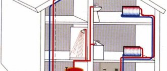
There are two types of heating systems - closed and open. In a closed system, the coolant circulates in a closed circle (see figure below). When open, it enters the heating system, gives off heat and leaves it.
Central heating in multi-storey buildings is an example of an open type system. Hot water enters the building, which passes through the radiators and gives off its heat. After this, it returns to the boiler room, thermal station, etc.
Closed-type heating works according to the following scheme:
- A heat source (boiler, heat pump, solar collector, etc.) heats the coolant;
- The coolant enters the heating system;
- Passing through heating devices (warm floors, radiators, fan coils), the coolant gives off heat and is cooled;
- After passing through the heating system, the coolant returns to the heat source.
There are also systems with natural and forced circulation. In the first case, the coolant moves through the pipes due to natural convection. In the second, it is pumped through the system by a circulation pump.
Closed heating system. The coolant circulates in a closed loop from the boiler to the heating devices.
Why do you need an expansion tank?
In closed heating systems, the volume of the coolant varies depending on its temperature (see table). For example, if water is heated from +40°C to +85 degrees, its volume will increase by 2.5%. This may seem like a small value to you, but it is dangerous for the heating system!
| ºС | Expansion coefficient, % | ºС | Expansion coefficient, % |
| 0 | 0.013 | 65 | 1.98 |
| 10 | 0.027 | 70 | 2.27 |
| 20 | 0.177 | 75 | 2.58 |
| 30 | 0.435 | 80 | 2.9 |
| 40 | 0.782 | 85 | 3.24 |
| 50 | 1.21 | 90 | 3.59 |
| 55 | 1.45 | 95 | 3.96 |
| 60 | 1.71 | 100 | 4.34 |
The fact is that water or coolant is not compressed - it puts pressure on pipes, fittings, and heating devices. Even slight expansion can lead to leaks. To compensate for this, an expansion tank is used.
Water in central heating systems does not differ in quality; it may contain air. Over time, it accumulates in the upper points of radiators, which is why they heat the room worse.
In closed systems, the coolant may react with the heating system material. which causes gas to be released. Over time, some coolant components may also decompose, releasing air or other gases.
If ordinary water circulates through your closed system, it can also cause air locks. It may contain impurities that react with the material of pipes, fittings and heating devices.
The expansion tank serves as a kind of catcher and reservoir for air and gases. Once they get into it, they no longer return to the general system. Installing a tank helps protect against airing of the system and you will not need to bleed air from the heating radiators.
How does an open expansion tank work?
An open expansion tank is simply a container partially filled with coolant. Sometimes there is not even a valve for air to escape, but just a hole.
Open expansion tanks have two big disadvantages. First, they are susceptible to corrosion because they come into contact with open air. Secondly, they can only be installed in systems with natural circulation.
If you have a circulation pump installed that circulates coolant through the system, then it will not go further than the open expansion tank. The coolant will simply fill the tank and overflow.
Operating principle of a closed (membrane) expansion tank
The design of a closed expansion tank differs from a closed one in the presence of a membrane. It is impermeable to air and coolant and divides the container into two parts.
The operating principle of a membrane expansion tank is simple. When the coolant heats up, it increases in volume. Under pressure, the membrane rises. This increases the total volume of the heating system and does not put additional pressure on it.
When cooled below a set temperature, the coolant contracts. The membrane lowers and the volume of the heating system decreases. This compensates for the vacuum created by compression of the coolant.
Restrictions
Manufacturers impose certain restrictions on the use of membrane expansion tanks, which depend on the design and materials used in the manufacture of the device. Manufacturers have clear requirements for the properties and composition of the liquid in the heating system. The content of, for example, ethylene glycol in an antifreeze solution is limited. The use of a membrane expansion tank at pressures exceeding permissible standards is prohibited. It is mandatory to install a safety group that controls and limits the pressure in the tank. The heating systems of autonomous heating apartments and private houses use equipment with an operating pressure of at least 3 bar.
Membrane tank design
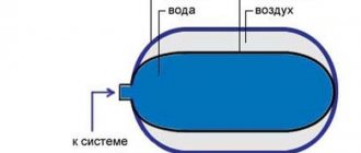
The design of a closed expansion tank is very simple. At the top there is a nipple through which air is pumped into the chamber. It is necessary to balance the pressure inside the container.
There is a rubber or polyurethane membrane located right in the middle of the tank. It is sealed and does not allow air or coolant to pass through. The membrane divides the tank into two parts. The lower chamber is designed for coolant, which gets there due to heating and pressure expansion. The upper one is for air under pressure, which prevents the coolant from immediately filling the entire cavity.
The internal structure of the expansion tank is membrane (closed) type.
Possible breakdowns
With prolonged use, the membrane may burst.
During operation of the equipment, owners are advised to inspect the housing for leaks and damage every six months. It is also necessary to measure the pressure in the gas chamber. The condition of the membrane is checked once every 2 years. If there is no use for a long time, the water is drained from the tank.
Common faults:
- Pressure drop in the gas compartment - it is necessary to pump air through the nipple using a pump.
- Damage to the housing - mechanical stress or corrosion can cause a crack to appear. The seal of the container can be restored at a service center.
- Leaking from the air valve - due to high loads and hot water, the rubber may crack. It is better to replace the damaged part in a timely manner.
You can repair the equipment yourself. To replace the membrane, you will need to drain the water, remove the container and relieve the pressure. Then unscrew the flange bolts holding the rubber part. The old membrane is removed and replaced with a new one. All procedures are carried out in reverse order.
Air pressure in the tank
The water or coolant in the heating system is always under pressure. In private houses it is 1.6-2 atm., in multi-storey houses - many times more. To ensure that the coolant does not lose pressure during normal operation, the upper part of the expansion membrane tank must be filled with air.
The air pressure in the upper chamber should be 0.2 atm. lower than the coolant pressure in the system. A regular bicycle or car pump is suitable for pumping air. The only thing you may need is an adapter.
At the top of the expansion tank there is a nipple with a spool. The operating principle is the same as in car or bicycle wheels. To deflate the air, just press the small tongue inside it.
Some manufacturers fill the tank not with air, but with nitrogen. In fact, this will not change the effectiveness of its work at all. This is an advertising ploy - they are trying to force you to buy more expensive equipment.
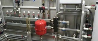
Connection diagrams for hydraulic tanks
For a hot water supply system, the expansion tank is installed in the section of the circulation line, the suction line of the pump, closer to the water heater.
The tank is equipped with:
- pressure gauge, safety valve, air vent - safety group;
- shut-off valve with a device that prevents accidental shut-off.
In a water supply system where water heating equipment is present, the device takes on the functions of an expansion tank.
Installation diagram in the hot water system: 1 – hydraulic tank; 2 – safety valve; 3 – pumping equipment; 4 – filtration element; 5 – check valve; 6 – shut-off valve
In the cold water system, the main rule when installing a hydraulic accumulator is installation at the beginning of the piping, closer to the pump.
The connection diagram must include:
- check valve and shut-off valve;
- security group.
Connection schemes can be very different. The connected hydraulic tank normalizes the operation of the equipment, reducing the number of pump starts per unit of time and thereby extending its service life.
Installation diagram in a cold water system with a well: 1 – tank; 2 – check valve; 3 – shut-off valve; 4 – relay for pressure regulation; 5 – pumping equipment control device; 6 – security group
In a scheme with a booster pumping station, one of the pumps runs constantly. This system is installed for houses or buildings with high water consumption. The hydraulic tank here serves to neutralize pressure surges, and to accumulate water, a container of as large a volume as possible is installed.
Calculation of the expansion tank using the formula
If you do not want to go into details, you can install a tank with a capacity of 10% of the total coolant volume. But sometimes it’s better to calculate everything exactly. By equipping a large heating system, you can save a lot.
To calculate the required volume of the expansion tank, you need to know the following:
- Minimum coolant temperature;
- Maximum coolant temperature;
- Heating system volume;
- The percentage of ethylene glycol or propylene glycol in the coolant.
Important!
If you are going to heat a house or cottage where you do not live permanently, be careful when selecting the type of coolant. They have different freezing temperatures and expansion coefficients.
To calculate the volume of the expansion tank you need to use the formula:
V = V1 x ( Q – Q1)
In this formula:
- Q1 – expansion coefficient at minimum temperature (see tables below);
- Q – expansion coefficient at minimum temperature (see tables below);
- V1 – volume of coolant in the heating system in liters;
- V – volume of the expansion tank in liters.
If an expansion tank is already installed in the heat source, then it must be taken into account. To do this, subtract the built-in capacity from the obtained “V” value. The resulting number is the required volume of your expansion tank.
Important!
If you have a forced circulation heating system, the minimum total capacity of the expansion tank is 15 liters.
Thermal expansion coefficient of ethylene glycol solution
| t, °С | 10% | 20% | 30% | 40% | 50% | 60% | 70% | 80% | 90% | 100% |
| 0 | 0.00013 | 0.0032 | 0.0064 | 0.0096 | 0.0128 | 0.016 | 0.0192 | 0.0224 | 0.0256 | 0.0288 |
| 10 | 0.00027 | 0.0034 | 0.0066 | 0.0098 | 0.013 | 0.0162 | 0.0194 | 0.0226 | 0.0258 | 0.029 |
| 20 | 0.00177 | 0.0048 | 0.008 | 0.0112 | 0.0144 | 0.0176 | 0.0208 | 0.024 | 0.0272 | 0.0304 |
| 30 | 0.00435 | 0.0074 | 0.0106 | 0.0138 | 0.017 | 0.0202 | 0.0234 | 0.0266 | 0.0298 | 0.033 |
| 40 | 0.0078 | 0.0109 | 0.0141 | 0.0173 | 0.0205 | 0.0237 | 0.0269 | 0.0301 | 0.0333 | 0.0365 |
| 50 | 0.0121 | 0.0151 | 0.0183 | 0.0215 | 0.0247 | 0.0279 | 0.0311 | 0.0343 | 0.0375 | 0.0407 |
| 60 | 0.0171 | 0.0201 | 0.0232 | 0.0263 | 0.0294 | 0.0325 | 0.0356 | 0.0387 | 0.0418 | 0.0449 |
| 70 | 0.0227 | 0.0258 | 0.0288 | 0.0318 | 0.0348 | 0.0378 | 0.0408 | 0.0438 | 0.0468 | 0.0498 |
| 80 | 0.029 | 0.032 | 0.0349 | 0.0378 | 0.0407 | 0.0436 | 0.0465 | 0.0494 | 0.0533 | 0.0552 |
| 90 | 0.0359 | 0.0389 | 0.0417 | 0.0445 | 0.0473 | 0.0501 | 0.053 | 0.0557 | 0.0584 | 0.0613 |
| 100 | 0.0434 | 0.0465 | 0.0491 | 0.0517 | 0.0543 | 0.0569 | 0.0595 | 0.0621 | 0.0647 | 0.0673 |
Volume expansion coefficient of propylene glycol
| t, °С | 0% | 10% | 20% | 30% | 40% | 50% | 60% | 70% | 80% | 90% | 100% |
| 0 | 0.00013 | 0.00014 | 0.00015 | 0.00015 | 0.00017 | 0.000175 | 0.000185 | 0.00019 | 0.0002 | 0.00021 | 0.00023 |
| 10 | 0.00027 | 0.00029 | 0.00031 | 0.00032 | 0.00035 | 0.00036 | 0.00038 | 0.0004 | 0.00042 | 0.00044 | 0.00047 |
| 20 | 0.00177 | 0.0019 | 0.00203 | 0.00208 | 0.0023 | 0.00239 | 0.00252 | 0.00262 | 0.00275 | 0.00288 | 0.0031 |
| 30 | 0.00435 | 0.00467 | 0.005 | 0.00511 | 0.00565 | 0.00587 | 0.0062 | 0.00644 | 0.00676 | 0.00707 | 0.00761 |
| 40 | 0.00782 | 0.0084 | 0.00899 | 0.00919 | 0.01017 | 0.01056 | 0.01114 | 0.01157 | 0.01216 | 0.0127 | 0.01368 |
| 50 | 0.0121 | 0.013 | 0.01391 | 0.01421 | 0.01573 | 0.01633 | 0.01724 | 0.0179 | 0.01881 | 0.01966 | 0.02117 |
| 60 | 0.0171 | 0.01838 | 0.01966 | 0.02009 | 0.02223 | 0.02308 | 0.02437 | 0.0253 | 0.02659 | 0.02779 | 0.02992 |
| 70 | 0.0227 | 0.0244 | 0.0261 | 0.02667 | 0.02951 | 0.03064 | 0.03235 | 0.0336 | 0.0353 | 0.03689 | 0.03972 |
| 80 | 0.029 | 0.03117 | 0.03335 | 0.03407 | 0.0377 | 0.03915 | 0.04132 | 0.04292 | 0.04509 | 0.04712 | 0.05075 |
| 90 | 0.0359 | 0.03859 | 0.04128 | 0.04218 | 0.04667 | 0.04846 | 0.05116 | 0.05313 | 0.05582 | 0.05834 | 0.06282 |
| 100 | 0.0434 | 0.04665 | 0.04991 | 0.05099 | 0.05642 | 0.05859 | 0.06184 | 0.06423 | 0.06749 | 0.07052 | 0.07595 |
In order to determine the amount of coolant in the heating system, you need to take into account the volume:
- Connected devices (radiators, underfloor heating, etc.);
- Pipes;
- Collector (comb);
- Heat source (for example, how much coolant is in the boiler or boiler coil).
The volume of pipes can be calculated using the formula:
V = L x 0.0785 x D x D
In this formula:
- L – heating pipe length;
- D – diameter in cm;
- V is the volume of coolant in the pipe in liters.
You can see the volume of coolant in the batteries in the specifications or instructions for them. If there are none, you can find out the amount of coolant in the publication “The volume of water in a heating radiator - aluminum, cast iron, bimetallic.”
Features of choice
It may seem to you that the expansion tank has a simple design and you can choose it only based on volume. But there are a few more points to consider:
- The membrane material must be resistant to reagents and additives used in coolants;
- The inside of the tank must be covered with high-quality paint or other coating.
- The protective coating on the inside of the container should not react with the coolant;
- The membrane must be resistant to high temperatures;
- The maximum permissible pressure in the tank must correspond to the characteristics of your heating system;
- All connections and seams must be resistant to high pressure and water hammer.
Differences from a hydraulic accumulator
The design of sealed expansion tanks is similar to the design of hydraulic accumulators, however, the purposes of these devices are different. The expansion tank compensates for the expansion of water that occurs due to heating in the heating system. The hydraulic accumulator accumulates the volume of water under pressure in a water supply system that has a pressure pump in order to reduce the frequency of activation of this pump and smooth out water hammer. In addition, more often than not, inside the accumulator there is a bulb made of food-grade rubber. It is this that is pumped with water; as a result, the water does not come into contact with the tank body. The expansion tank for heating systems is made with a membrane made of technical rubber. It divides the housing into two compartments, and the coolant has contact with the housing.
Types of hydraulic accumulators
For heating systems, manufacturers produce tanks that differ in membrane design.
Membranes for expansion tanks are divided into:
- balloon;
- diaphragm.
The diaphragm membrane is a permanent partition made, most often, of thin metal or elastic polymer.
The main difference between this option is its small internal capacity and the ability to compensate for minor pressure drops in the system.
If such a tank malfunctions, it must be completely replaced.
The advantages of such devices include simplicity of design, reliability in operation and low price.
The balloon-type membrane is a container installed inside the tank made of high-quality rubber that is resistant to significant temperature changes.
A flange fastening of the membrane is used, which allows for its simple and quick replacement (how to install pipeline shut-off valves with your own hands is written here).
The advantages of balloon membranes include:
- wide range of operating pressures at which the use of a sealed expansion tank is allowed;
- the ability to replace the membrane , thanks to which repairing the device (about a manual pipe cutter for plastic pipes is written here) becomes faster and cheaper;
- ease of setting the minimum (set) pressure for any system.
The model ranges of tanks with replaceable membranes produced by manufacturers cover a wide range of not only pressures, but also volumes.
At the same time, devices are available in various designs, for horizontal and vertical installation, with mounting on building structures or installation on legs, which significantly increases the flexibility of designing heating systems.