A hydraulic accumulator (expansion membrane tank) serves to maintain pressure in a pressure water supply system, and when used in conjunction with a pressure switch, allows you to create an automatic station based on a submersible or surface pump. The main purpose of the hydraulic accumulator in the system is to maintain and smoothly change the fluid pressure in the system.
Additional functions performed by the hydraulic accumulator are as follows:
- Protection against water hammer (changes in fluid pressure caused by an instantaneous change in its speed)
- Ensuring a minimum supply of water
- Limitation of intermittent pump starts
Thus, it is the hydraulic accumulator that makes it possible to use a pressure switch and automate the water supply process. Without a hydraulic accumulator, the relay cannot work correctly, since an instantaneous change in pressure in the system (at the moment of opening a tap, disconnecting or connecting new consumers, turning a pump on or off, etc.) would cause the relay to constantly operate. And this, in turn, leads to instability of supply, overheating or breakdown of the electric motor, and breakdown of the relay.
Since water is practically incompressible, turning on a pump in a system with a pressure relay, but without a hydraulic accumulator, would cause an instant increase in pressure in the system and the relay would immediately react to this and turn off the pump. On the other hand, when the tap was opened, the pressure would immediately drop and the relay would react and turn on the pump.
Water compressibility coefficient = 5 x 10^10 1/ Pa. Those. An increase in water pressure (the pressure created by the pump) practically does not cause a change in its volume (these are hundredths of a percent). Therefore, the pressure in the system would change at a high speed, which would cause the relay to constantly operate.
It must be clearly understood that the hydraulic accumulator does not create any pressure and does not pump water to the consumer itself - all this is done by the pump. It only maintains the liquid pressure that is created in it by the pump and supplies water at that moment in time while the consumer’s tap is open and the pump is not turned on. For example, the question “What volume of hydraulic accumulator do I need if I have two showers?” not entirely correct. Because when using a shower (one or two), the hydraulic accumulator supplies water only until the pump is turned on, and then only the pump supplies water for the remaining time of use. And it will stop only after all the taps are closed and the pressure in the tank rises to the shutdown pressure.
Sometimes it happens that the pump turns off even while consumers are using water. However, this mode of operation is undesirable (since after a short time the pump will have to turn on again) and indicates that the selection of the pump and/or the settings of the entire system are incorrect (in most such cases it is necessary to change the settings of the pressure switch).
Any hydraulic accumulator is divided by a membrane into two cavities: air and water. By supplying water under pressure into the water cavity of the tank, the membrane expands and compresses the air in the air cavity. Thus, the membrane is balanced by pressure on both sides (P1V1 = P2V2). The pressure will increase until the pump is switched off at the pressure switch setting (pump cut-off pressure). At the moment water flow begins, air presses on the membrane, thereby pushing water out of the accumulator. The water pressure slowly drops and when the pump activation pressure is reached, the relay will close the contacts and the pump will start. This is the schematic diagram of the automatic operation of the pump together with a hydraulic accumulator and a pressure switch.
The structure of the hydraulic accumulator and its components
Water pressure switch for a pump
To start the device, it is necessary to immerse the pump (and it can be of a submersible or surface type) in water, while maintaining a specific level of pressure supplied to the elastic membrane tank.
Hydraulic tanks have a certain operating principle, but the design will function correctly if:
- The instructions were used during installation;
- Everything is carefully sealed;
- The product fully complies with the GOST standard for its quality.
The container expands and the air pressure increases, located in the space between the membrane cavity and the inside of the tank housing. An increase in pressure helps to turn off the relay, due to which the pump operates, and at this time water flows through the distribution points installed in the house.
This means that the air pressure decreases and the relay turns on again for dialing, but this happens at a certain level set by the manufacturer. After switching on, the cycle repeats again until the pump is blocked again.
How to choose
The main working body of the hydraulic tank is the membrane. Its service life depends on the quality of the material. The best membranes today are made from isobutated rubber (also called food grade). The body material only matters in membrane-type tanks. In those in which a “pear” is installed, water comes into contact only with rubber and the material of the body does not matter.
The flange should be made of thick galvanized steel, but better - stainless steel
What's really important about bulb tanks is the flange. It is usually made of galvanized metal. In this case, the thickness of the metal is important. If it is only 1 mm, after about a year and a half of operation, a hole will appear in the metal of the flange, the tank will lose its tightness and the system will stop working. Moreover, the warranty is only one year, although the stated service life is 10-15 years. The flange usually deteriorates after the warranty period expires. There is no way to weld it - the metal is very thin. You have to look for a new flange at service centers or buy a new tank.
So, if you want the accumulator to last a long time, look for a flange made of thick galvanized or thin, but made of stainless steel.
Hydraulic accumulator device, principles of operation
Water pressure switch for pump
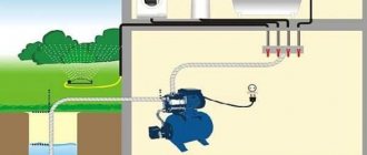
To better understand the functions of individual elements, it is necessary to consider the system as a whole.
From a well or other source, water is pumped into the main pipeline. To prevent it from moving in the opposite direction, a safety valve is installed. Shut-off valves are installed in the required places. It is used for preventive maintenance, adjustments, and replacement of failed units.
Water flows through the pipeline into a special container, which performs several functions:
The main working element of such a container is a flexible partition. But the initial pressure in the tank itself is created by the pump. With appropriate equipment, it is controlled from a special remote control. Data is received there from the pressure switch for the hydraulic accumulator.
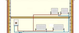
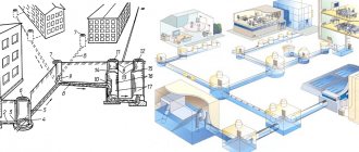
Above is part of a smart home class diagram. It connects to the general control system. In practice, more economical solutions are often used.
To successfully solve the identified problems, the following designs of hydraulic accumulators are used:
This picture shows another important element, the flow filter. It prevents the entry of mechanical contaminants, damage to the relay and blocking of its drive mechanisms. The increased tank capacity is useful not only for high daily consumption. It will reduce the number of pump starts/stops, which will have a positive impact on the durability and reliability of the system.
The standard method for calculating tank volume (VT) uses the following formula:
OB=16.5 x RV/KV x CD x 1/DVK, where:
In order not to embarrass oneself when living year-round, a tank with a capacity of 40-60 liters is sufficient for a family of three. Similar advice is given by specialized experts. In fact, it is better to make a more accurate calculation using the above method. The results obtained should be increased taking into account guest visits and other situations accompanied by increased water consumption. This approach will help you purchase a hydraulic accumulator for water supply, the price of which will correspond to the technical characteristics and needs of future users.
When placing the tank at the highest point of the structure, the force of gravity will be used. But we must take into account that the room must be reliably protected from adverse external influences. It maintains temperatures above 0°C all year round.
It is necessary to remember about the increase in mechanical loads. A large water tank weighs a lot, so sometimes additional reinforcement of the structure’s load-bearing frame is required. For these reasons, large containers are often installed in the basement.
Related article:
How to install a pressure switch for a hydraulic accumulator
Before performing work operations, it is necessary to clarify the general requirements. In order for the water supply system to function optimally, the pressure difference for turning the pump on and off is set within the range from 0.9 to 1.8 atm. Exceeding it will increase energy consumption.
To calculate what pressure should be in the hydraulic accumulator (DHA), use the formula DHA = (B+6.5)/10, where:
The process of connecting a pressure switch to a hydraulic accumulator
For study, this article discusses a mechanical pressure switch for a hydraulic accumulator. This design is repeated in modifications by different manufacturers, with relatively minor changes.
This product is connected to the water supply system in assembled form. Flexible tubing designed for appropriate pressure levels can be used to place it in a convenient location. If necessary, use transition fittings. Upon completion of installation, the tightness of the threaded connections is checked experimentally.
The electrical connection can be made directly to the pump power supply circuit. Use wires designed for appropriate power. To eliminate errors, it is recommended to use products with color braiding. The “earth” standard is a combination of yellow and green. The electric motor is connected to a 220 V network through an automatic device, which ensures quick shutdown in the event of a short circuit.
All electrical installation work is carried out with the voltage turned off. It is necessary to exclude accidental supply of voltage during the process of adjusting the pressure switch for the hydraulic accumulator.
Connecting the hydraulic tank
Characteristics of water pressure switch for pumps
A hydraulic tank is the second name for a hydraulic accumulator. It can be connected to the water supply system in various ways. The choice of a suitable connection scheme mainly depends on the capacity in which the device will be used, as well as what tasks it will perform. It is worth considering several of the most popular connection methods.
Using a surface pump
It is worth examining step by step how the hydraulic accumulator is connected to the system if there is a surface pump subtype.
- First you need to check the air pressure in the inside of the tank. It should be 0.2-1 bar less than the parameter on the relay.
- Then you should prepare the equipment for connection. In this situation, the equipment means: a fitting, a pressure gauge, a tow with a sealing compound, a relay responsible for pressure.
- You need to connect the fitting to the tank. The connection area can be a hose or a flange with a bypass valve.
- Then you should screw on the other devices one by one.
To determine the absence of leaks, you need to run the equipment in test order
When connecting the relay, which is responsible for regulating the pressure, it is important to inspect all the marks. Under the cover there are contact connections - “network” and “pump”
Do not confuse the wires. If there are no marks under the relay cover, then it is better to contact a professional to connect it to avoid a serious mistake.
With submersible pump
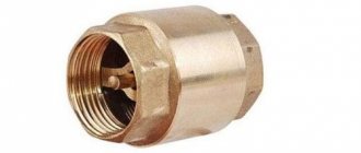
The submersible or deep-well type of pump differs from the above option in that it is located in a well or dug well, in other words, in the area from which water is sent to the home, and in the above situation, to the hydraulic accumulator. One detail is very important here - the check valve. This element is designed to protect the system from liquid penetration back into the well or well. This valve is fixed on the pump next to the pipe. For this purpose, a thread is cut in its lid.
First of all, fix the check valve, and then connect the hydraulic accumulator itself to the system.
The diagram is as follows:
- to measure the length of the pipe running from the deep-well pump to the extreme point of the well, you basically take a string with a weight;
- the load is lowered to the bottom, and a mark is made on the rope to mark the edge of the well at the top;
- after removing the rope, you can calculate the length of the pipe from the lowest plane to the top;
- you need to subtract the length of the well, as well as the distance from the section where the pipe passes into the soil to the highest level of the well;
- In addition, it is very important to take into account the immediate location of the pump (pump) - it should be located 20–30 cm from the bottom.
Features of mounting a boiler on a thin wall
Ideally, the water heater should be mounted on strong brick, concrete or block walls, since the device, together with water, has quite a lot of weight. But sometimes the device needs to be hung on a thin plasterboard, frame, wood, aerated concrete or foam block base.
First, it needs to be well insulated from heat, for example, with profiled iron, which is used for roofing.
In other cases, special fastenings are used:
- spiral nylon dowels;
- metal fasteners for mounting boilers with a capacity of 100 liters or more.
If you plan to hang the water heater on a wall made of foam concrete blocks, you will need metal dowels or special chemical (adhesive) anchors for foam concrete.
Chemical anchor is a universal fastener that can withstand high loads. It is environmentally safe and resistant to low temperatures.
The expansion dowel is held in the wall due to frictional forces in the expansion joint, and the chemical anchor is held due to the adhesion of a special adhesive composition.
Attachment to an adhesive anchor is carried out in the following way:
- A hole is drilled to expand the channel by rotating the drill at an angle in different directions.
- Concrete dust is removed from the hole.
- The hole is filled with a quick-hardening mixture, into which a fastening sleeve or threaded pin is inserted.
The resulting cone-shaped plug provides fairly high fastening strength. For installation in hollow structures, an anchor sleeve is inserted into the hole, and a pin is screwed into it
The pressure in the accumulator is 24 liters
You can often hear the question, what pressure should be maintained in a 24-liter hydraulic accumulator? And if the tank is large, then what is the pressure in the accumulator: 50 liters, or 100 liters? Answering this question, we can answer in the affirmative that the pressure in the tank does not depend in any way on the volume of the tank. That is why the air pressure in a hydraulic accumulator of 50 liters and even 150 liters must be maintained at exactly the same values.
The thing is that the hydraulic accumulator for water supply systems works in conjunction with pumping equipment. Accordingly, we set up the water supply system so that when the tap is opened, the pump turns on and water flows. When closing the tap, we therefore want the pump to turn off. A small, inconspicuous device is responsible for such comfort - a pressure switch or flow sensor:
The pressure switch monitors, pardon the pun, pressure. So, when the tap is closed, the pumping station continues to operate, increasing water pressure in the water supply pipes. Having reached a certain value, the relay opens the contacts and the pump turns off. The pressure value, of course, can be different, but at least not exceed the threshold for rupture of pipes, pipe connections, or the hydraulic part of the pump.
Typically, the pressure in the water supply system of a country house is considered quite sufficient at 2.5 atmospheres. A pressure of only 2 atmospheres is enough for: showering, washing dishes, other everyday needs and stable operation of the washing machine. Thus, answering the question of what pressure in the accumulator needs to be maintained, we can say with confidence - any below the pressure switch response threshold, otherwise the pump will turn off faster than the accumulator is pumped.
One of the rules states that the correct pressure set in the tank must be 10% below the threshold. Homeowners usually play it safe a little and set the value lower by 12 – 15%. The standard settings set at the factory are usually 1.5 atmospheres for any tank. Over time, the pressure in the vessel drops slightly, since there are acceptable losses through the spool. You can pump up the tank using a regular bicycle pump, after completely draining the water from it.
Optimal performance
The functioning of the water supply network and the life of the storage tank depend on several factors:
- The correct choice of the maximum and minimum pressure at which the automatic switching on of the pump is triggered.
- Correctly setting the air pressure level in the tank.
When performing independent checks and adjustments of indicators, you should follow the recommendations of specialists. The basic rule is that the air pressure in the hydraulic storage tank must be lower than the minimum pump start pressure. The difference in indicators is 10-12%. Following the recommendation allows you to save a small amount of water until the next time you turn on the unit. Example: if the pumping station automatically starts working at 2 bar, the air pressure should be 2-0.2 = "1.8" bar.
The air pressure in the storage tank does not depend on its volume. The average for containers measuring 24-150 l is 1.5 bar, 200-500 l - 2 bar. The initial factory air injection of 1.5 atmospheres in conditions of low water consumption of a one-story building can be reduced to 1 atmosphere. Low pressure in the pipes reduces wear and tear on the system, but limits the use of plumbing fixtures. Reducing the pressure to less than 1 bar will result in excessive stretching of the rubber bulb. The membrane will come into contact with the metal casing. Contact will cause accelerated wear of the rubber.
Excessive air pressure (more than 1.5 bar) is also not desirable. It will take up most of the tank, reducing the amount of water drawn. There will also be an increased load on the pipes and components of the water supply system.
Pressure calculation
To calculate the optimal air pressure in the tank, there is a formula: P=”(Hmax+6)/10,” where
- P – air pressure in atmospheres;
- Hmax is the distance to the highest point of the home water supply network.
The highest point of analysis is the shower on the top floor of the building. The distance from it to the installation site of the pressure tank is measured. The larger the gap, the higher the pressure required to lift the water. The use of numbers will add clarity to the calculation. For a building with a height of 2 floors, the Hmax value will be 7 m. The pressure will be P=”(7+6)/10=1.3″ atmospheres. For a height of 10 m, a pressure of 1.8 atmospheres is required.
Before purchasing a hydraulic accumulator, the volume of the device is calculated. Calculations take into account:
- maximum water flow;
- number of pump starts per hour;
- air pressure in the tank;
- lower and upper pressure limits for pump activation;
- coefficient related to pump power.
After installing the membrane tank, you will need to set the minimum and maximum threshold for the automation (pressure switch). The volume of water coming from the hydraulic accumulator depends on the difference between the maximum and minimum indicators. Increasing the parameter increases the efficiency of the device, but leads to rapid wear of the membrane. For private houses, a difference of 1-1.5 bar is recommended.
The minimum pressure in the membrane (Pmin) should be 10% higher than that of the air in the tank cavity. For stable operation of the system, the pressure drop must be 0.5 bar or higher. This value is taken into account when calculating Pmin. The upper response limit (Pmax) is calculated based on the characteristics of the pump - the pressure value is divided by 10. The calculated value does not correspond to the real one due to changes in the declared parameters of the unit associated with wear. It is recommended to take the upper level indicator 30% less than the pressure characteristic.
The principle of operation of a hydraulic accumulator in a water supply system and its capacity
When equipping the water supply system with automation, you need to first check it for leaks and malfunctions, and if there are any, then determine the reasons for their occurrence, which will allow for more competent maintenance. It is worth noting that some people prefer to install a homemade hydropneumatic receiver.
However, when assembling it with your own hands, you need:
- Strict adherence to technology;
- Compliance with recommendations from specialists;
- Use only high-quality materials.
In this case, you should not pay attention to such points as, for example, what color the tank is, blue or red. After collection, you need to conduct a full review of the structure to identify problems, which directly determines its validity. As for the capacity of the tank in the accumulator, this directly depends on how many points water is supplied to in the house.
When choosing tank types based on capacity, you need to immediately decide on the location. When installing vertically, it is necessary to add a third of the volume to the design pressure value, due to which the pump will turn on much less often. However, it is worth considering the fact that the room where the equipment will be installed must be warm and without sudden temperature changes, which can lead to damage to the device.
Crimping
This term refers to a control test that confirms the performance of equipment and plumbing. When it is carried out in an apartment or private house, a special device is used, with which water is pumped into the system and the pressure is manually increased.
This is done in the following order:
- The pressure tester is connected to a water supply line filled with water. The pressure rises to 4-5 atmospheres.
- The system is inspected to identify leaks and eliminated as soon as they are identified.
- A further increase in pressure to 10-12 atmospheres is carried out after their elimination.
- In this state, the heater and pipelines to it are left for a day.
Purpose and device
In order to maintain constant pressure in the water supply system of a private house, two devices are needed - a hydraulic accumulator and a pressure switch. Both of these devices are connected to the pump through a pipeline - the pressure switch is located in the middle between the pump and the accumulator. Most often it is located in close proximity to this tank, but some models can be installed on the pump body (even submersible). Let's understand the purpose of these devices and how the system works.
A hydraulic accumulator is a container divided into two halves by an elastic bulb or membrane. In one there is air under some pressure, in the second water is pumped. The water pressure in the accumulator and the amount of water that can be pumped into it are regulated by the amount of pumped air. The more air there is, the higher the pressure is maintained in the system. But at the same time, less water can be pumped into the container. Usually it is possible to pump no more than half the volume into the container. That is, no more than 40-50 liters can be pumped into a hydraulic accumulator with a volume of 100 liters.
For normal operation of household appliances, a range of 1.4 atm - 2.8 atm is required. To maintain such a framework, a pressure switch is required. It has two response limits - upper and lower. When the lower limit is reached, the relay starts the pump, it pumps water into the accumulator, and the pressure in it (and in the system) increases. When the system pressure reaches the upper limit, the relay turns off the pump.
In a scheme with a hydraulic accumulator, water is consumed from the tank for some time. When enough has flowed out for the pressure to drop to the lower response threshold, the pump will turn on. This is how this system works.
Pressure switch device
This device consists of two parts - electric and hydraulic. The electrical part is a group of contacts that closes and opens turning the pump on/off. The hydraulic part is a membrane that exerts pressure on the metal base and springs (large and small) with the help of which the pump on/off pressure can be changed.
The hydraulic outlet is located on the back of the relay. This can be an outlet with an external thread or with an American-type nut. The second option is more convenient during installation - in the first case, you either need to look for an adapter with a union nut of a suitable size or twist the device itself, screwing it onto the thread, but this is not always possible.
The electrical inputs are also located on the back of the case, and the terminal block itself, where the wires are connected, is hidden under the cover.
Types and varieties
There are two types of water pressure switches: mechanical and electronic. Mechanical ones are much cheaper and are usually preferred, while electronic ones are mainly delivered to order.
| Name | Pressure adjustment limit | Factory settings | Manufacturer/country | Device protection class | Price |
| RDM-5 Gilex | 1- 4.6 atm | 1.4 - 2.8 atm | Gilex/Russia | IP 44 | 13-15$ |
Italtecnica РМ/5G (m) 1/4″ 1 - 5 atm 1.4 - 2.8 atm Italy IP 44 27-30$ Italtecnica РТ/12 (m) 1 - 12 atm 5 - 7 atm Italy IP 44 27- 30$ Grundfos (Condor) MDR 5-5 1.5 - 5 atm 2.8 - 4.1 atm Germany IP 54 55-75$ Italtecnica PM53W 1″ 1.5 - 5 atm
Italy
7-11 $ Genebre 3781 1/4″ 1 - 4 atm 0.4 - 2.8 atm Spain
7-13$
The difference in prices in different stores can be more than significant. Although, as usual, when buying cheap copies, there is a risk of running into a fake.
Optimal parameters
The main factors on which the operation of the water supply network and the service life of hydraulic equipment depend are the following:
- Correct calculation of the maximum and minimum pressure values at which the pump should turn on (off).
- Correct pressure adjustment in the receiver.
The air pre-injection pressure is 1.5 – 2 bar (depending on the tank volume). The determination of the air pressure value for operation in tandem with a specific pumping station is made based on the factory parameters of the pressure switch. The average pressure at which the pump turns on is from 1.4 to 1.8 bar. The shutdown threshold is usually in the range of 2.5 - 3 bar. The optimal air pressure should be 10-12% less than the pump activation pressure.
If these requirements are met, after turning off the hydraulic pump, a certain amount of water is guaranteed to be retained in the storage tank, sufficient to create a stable pressure until the next start of the pump.
Recommendations for use
Once installed, it must be properly maintained. About once a month you should check the pressure switch settings and adjust them if necessary. In addition, you need to check the condition of the housing, the integrity of the membrane and the tightness of the connections.
The most common failure in hydraulic tanks is diaphragm rupture. Constant cycles of tension and compression eventually lead to damage to this element. Sudden changes in pressure gauge readings usually indicate that the membrane has ruptured and water is entering the “air” compartment of the accumulator.
To make sure there is a breakdown, you just need to bleed all the air from the device. If water follows it from the nipple, then the membrane definitely needs to be replaced.
Fortunately, these repairs are relatively easy to make. To do this you need:
- Disconnect the hydraulic tank from the water supply and power supply.
- Unscrew the bolts that hold the neck of the device.
- Remove the damaged membrane.
- Install a new membrane.
- Reassemble the device in reverse order.
- Install and connect the hydraulic tank.
Upon completion of the repair, the pressure settings in the tank and pressure switch should be checked and adjusted. The connecting bolts must be tightened evenly to prevent the new membrane from warping and to prevent its edge from sliding inside the hydraulic tank housing.
Replacing the accumulator membrane is relatively easy, but you need to make sure that the new membrane is the same as the old one
To do this, install the bolts in the sockets, and then alternately make literally a couple of turns of the first bolt, move on to the next, etc. Then the membrane will be pressed against the body equally along the entire circumference. A common mistake made by beginners in repairing a hydraulic accumulator is the incorrect use of sealing agents.
The installation site of the membrane does not need to be treated with a sealant; on the contrary, the presence of such substances can damage it. The new membrane must be exactly the same as the old one both in volume and configuration. It is better to first disassemble the hydraulic accumulator, and then, armed with a damaged membrane as a sample, go to the store for a new element.
If you liked the article, please share it
Previously on the topic:
Share
What pressure should be in the accumulator
There are several methods for accurately selecting the capacity of a hydraulic accumulator tank, but the main principle is the selection principle based on the capacity of the storage tank. The initial data are the number and nature of water consumption points, the power and type of pump, the maximum permissible number of its starts, the desired water pressure in the network
It is also important how much water from the tank can be used before the next time the pump is turned on, as well as during power outages. The permissible difference in water pressure is set during the process of setting the pressure switch
The water reserve in the accumulator (which usually amounts to up to half of its total capacity) can be determined with sufficient accuracy from the theoretical capacity of the tank and the pressure drop in it:
- For a tank up to 50 l, with a pressure difference of up to 1 atm - 15.0...12.5;
- For a tank up to 100 l, with a pressure difference of up to 1 atm - 30.0...16.5;
- For a tank of more than 100 liters, with a pressure difference of up to 1 atm - 70.0...55.0;
- For a tank up to 50 l, with a pressure difference of up to 1.5 at – 13.5...8.0;
- For a tank up to 100 l, with a pressure difference of up to 1.5 at - 25.0...20.0;
- For a tank of more than 100 liters, with a pressure difference of up to 1.5 atm - 55.0...40.0.
The volume of the hydraulic accumulator tank is determined with sufficient accuracy using the following practical relationships:
- For surface pumps with a power of up to 1 kW - at least 25 l;
- For surface pumps with a power of more than 1 kW - at least 50 l;
- For submersible pumps with a power of up to 1 kW - at least 20 l;
- For submersible pumps with a power of up to 1.5 kW - at least 50 l;
- For submersible pumps with a power of up to 5 kW - at least 100 liters.
The capacity of the hydraulic accumulator tank also depends on the number of water points and the number of people living in the house. For example, for a small family with modest needs (one tap in the kitchen and shower room, + bathroom), 50 liters will be enough, and if there is a bathroom, a capacity of at least 100 liters will be required.
The capacity of the device in question also depends on the location of its installation. A vertical hydraulic accumulator, which is mounted at the highest point of water intake (for example, at a height of 4.5...5 m), adds about a third to the design pressure value, which will allow the pump to turn on less often. However, it should be taken into account that the room for installing the hydraulic accumulator must have a minimum temperature difference, i.e., either be well insulated or be constantly heated during the cold season. Fluctuations in relative humidity should also be minimal.
The habit of selecting everything with a margin for the volume of the hydraulic accumulator is not suitable. The fact is that if the volume of water in the tank stagnates for a long time, then, firstly, the inner surface of the tank suffers, and, secondly, the quality of the water itself deteriorates (especially if the installation of the water supply scheme did not include the installation of biological filters) . In this case, you will have to frequently drain the water from the container, and a large hydraulic accumulator will be of little use.
Most manufacturers claim the ability of the housing and connecting fittings to withstand constant operating pressures of at least 10 at. When choosing, the nominal temperature rise of the water that the membrane material allows is also taken into account. For high-quality materials it cannot be less than 70...100°C.
The manufacturer of such products in our country is the Jeelex brand. Hydraulic accumulators from Aquasystem (Italy) and Reflex (Germany) are also popular.
How to choose tank volume
You can choose the tank volume arbitrarily. There are no requirements or restrictions. The larger the volume of the tank, the greater the supply of water you will have in case of a shutdown and the less often the pump will turn on.
When choosing a volume, it is worth remembering that the volume that appears in the passport is the size of the entire container. There will be almost half as much water in it. The second thing to keep in mind is the overall dimensions of the container. A 100 liter tank is a decent-sized barrel - about 850 mm high and 450 mm in diameter. You will need to find a place somewhere for it and the harness. Somewhere - this is in the room where the pipe from the pump comes. This is where all the equipment is usually installed.
If you need at least some guidelines to select the volume of a hydraulic accumulator, calculate the average flow rate from each water intake point (there are special tables or you can look at the data sheet for household appliances). Sum up all this data. Get the possible consumption if all consumers work simultaneously. Then figure out how many and which devices can work at the same time, calculate how much water will be consumed in a minute in this case. Most likely by this time you will have already come to some decision.
To make it a little easier, let’s say that the hydraulic tank volume of 25 liters is enough to meet the needs of two people. It will ensure the normal functioning of a very small system: a faucet, a sink and a small one. If you have other household appliances, the capacity must be increased. The good news is that if you decide that the current tank is not enough for you, you can always install an additional one.