Foundation drainage from Jheka
JhekaFORUMHOUSE Member
While it’s still hot and everything that can be dried out, it’s time to do drainage. Our groundwater is quite close; in winter, when the water freezes, heaving sometimes occurs under the blind area. Now under the blind area there is insulation, 100 mm EPPS, but, nevertheless, it was decided to do drainage.
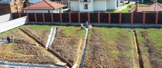
The watershed will begin from the entrance to the house, the pipes will go to the sides and along the entire perimeter. There is one concrete collector well planned, behind the fence opposite, with pumping of wastewater into a ditch.
The foundation is a monolithic shallow tape; a meter was removed from the Jheka blind area and a trench 40 cm wide was marked out to make digging easier.
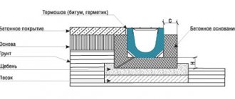
Application of drainage pipes
The most popular are pipes with diameters of 100 and 110 mm. This section is used in closed and open systems for draining surface and melt water in personal plots. It is advisable to purchase small-diameter products for flat areas, using them as side branches and end pipes. To correctly determine the diameter of the drainage pipe, the terrain features are taken into account:
- type of soil;
- degree of humidity;
- filtration coefficient;
- inflow volume;
- freezing, etc.
Please note that the width of the trench should be approximately 40 cm greater than the diameter of the pipe used.
Excavation
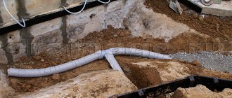
The top point of the drain was planned opposite the door, at 50 cm, but in the process 50 cm turned into 60 cm. At the same time, an underground electrical cable entry was organized. The slope in the trench is 1 cm per linear meter. For sampling in the lawn area, plywood and PE film were laid.
We performed a puncture.
Determining the depth of laying pipes based on the level of the surface to be cut
The main requirement: the route being laid must be below the level to which the soil freezes during periods of negative temperatures.
If the drainage system freezes, then during the period of snow melting or spring floods, melt water will not be able to leave the site, since the drainage pipes are located in the area of frozen soil
It is important to remember: the melting of ice in the pipes of the drainage system is much slower than the melting of ice on the surface of the site. And it is quite possible that the first spring rain will lead to flooding of the site or building on it
It should also be remembered that if the winters are snowy, snow is an excellent heat insulator; it protects the drainage system from freezing; if the cover is significant, the depth of freezing of the soil under it will be much less. But you shouldn’t count on this; it’s better to lay drainage pipes below the level to which the soil freezes in a given area.
To determine the exact depth for laying pipes below the freezing level, for each specific region you need to subtract 30 cm if the drainage pipes have a diameter of up to 50 cm. If you plan to use pipes with a larger cross-section - from 500 mm, you should subtract 500 mm.
This way we get the minimum depth for laying drainage pipe routes.
The values of soil freezing are indicated in special SNiP tables.
Let's look at the example of one of the sections of the Moscow region
According to the SNiP tables, the depth of soil freezing for the Moscow region, in particular for the settlement of Istra, is 1400 mm
pipes of small cross-section, 200 mm, are used on the site. According to the formula, we subtract 300 mm.
The final burial depth (minimum) is 1100 mm.
Components and materials
Drainage pipe in geotextiles, geotextiles for needle-punched trenches, heat-treated, width 1.5 m, density 150 g/m², drainage wells, covers, adapters. Crushed granite, fraction 5-20 and 5-40.
Filling with sand while maintaining the slope.
Jheka
The first thing I want to say to those who will do the drainage is to use only washed crushed stone and fractions of 20-40! No 5-20 like mine. Here is my crushed stone, which means unwashed.
A layer of crushed stone cushion on top of geotextile about 5 cm thick.
The next batch of crushed stone is also unwashed, but already of fraction 5-40, although it is too small.
By the way, crushed stone can be washed, especially if you have a high-pressure washer. And if crushed stone has been replaced with gravel out of necessity, and it is in clay, it is necessary to wash it. Otherwise, the clay will be washed away directly into the trench and silt up the geotextile.
resergelFORUMHOUSE Member
Definitely wash. I also have gravel in clay, washed with Karcher. I made a frame with a mesh, like for sifting sand, and washed it in portions, washing it for a long time - about two weeks every day.
Pipe Selection Options
Polyethylene pipes for drainage are selected taking into account a number of parameters, including type of material, type of pipe, perforation, diameter.
Material
Plastic pipes for drainage are made from the following materials:
- Polyethylene is the most common type, which is usually sold in the form of corrugated coils of up to 100 m. It has good frost resistance, but does not tolerate high temperatures (more than +45°C).
- Polypropylene is a heat-resistant and durable material that is usually sold in pieces. Has high rigidity.
- PVC is highly resistant to aggressive substances. Durable, heat-resistant, like the previous version.
The service life of each material, with proper selection and installation of pipes, averages about 50 years. The diameter of these pipes ranges from 63 mm to 630 mm, but the most popular series refers to the section 110-200 mm.
Perforation
Perforations are holes in drainage pipes through which water enters the system and is delivered to the drainage well. It can be partial or complete. By partial we mean the presence of perforations on only one side of the pipes. In this case, it should be taken into account that the product is laid with the perforation facing up.
Full perforation implies the presence of holes around the entire circumference. Therefore, its installation method is standard and requires only taking into account the basic standards of GOSTs and SNiPs.
In both cases, perforation can be performed either in the form of round holes or in the form of slots.
Diameter
The diameter of the pipes is responsible for the throughput of the pipe. The larger it is, the more moisture will be collected from the ground. When selecting a section, you need to take into account the type of soil, the depth and thickness of the groundwater layer, the amount of average annual precipitation, and so on. Typically, companies that lay drainage pipes take average values of these indicators. So they do:
- The main water supply is pipes with a cross section of 160-200 mm.
- Secondary branches with pipes with a diameter of 110 mm.
But as practice has shown, often smaller cross-sectional values of products can be effectively used in drainage in small areas.
Pipe design
This refers to single-layer and multi-layer products. Multilayer pipes are more rigid and can withstand heavy soil weight, so they are often used in places with heavy load on the soil or road surface.
Single-layer options are more flexible and are most often represented by corrugated products. Laying them is much easier, especially if there is a heterogeneous soil composition. But such options are usually used in areas with small or medium loads on the ground or road surface.
Large-diameter drainage pipes usually have high rigidity, so products with a large cross-section and high drainage capacity are used for drainage of areas where large enterprises, factories, airport runways, and so on are located.
Installation of drainage system and backfilling
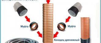
We continue - inserting the coupling into the well (first, with a thick drill, to the required diameter, with a jigsaw).
Drainage pipe laid on top of crushed stone preparation.
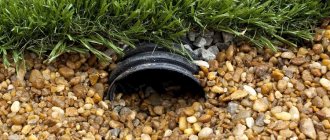
Rotary, also known as an inspection well.
On rotary wells, I swapped the bottom and lids - it is easier to collect silt deposits from a flat surface, if necessary.
To fill the drainage trench, Jheka used sifted crushed stone, to save money, he narrowed the trench a little on the sides with sand. The thickness of the crushed stone layer in the backfill varies between 5-7 cm, the crushed stone is covered with geotextiles, and sand is placed on top, in a layer of about 20 cm.
The remaining centimeters were filled partly with earth, partly with river and quarry sand.
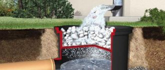
Results
Groundwater usually has a low rise rate. Therefore, proper installation of the system with timely collection of wastewater from the receiving well will ensure long-term drainage operation. The diameter of the drainage pipes is selected based on a number of parameters, the first of which is throughput. So, to drain a small summer cottage, a cross-section of 63 mm will be sufficient, while for large plots of land, industrial facilities, including airports, roads with heavy traffic of heavy vehicles, diameters of 200 mm are used.
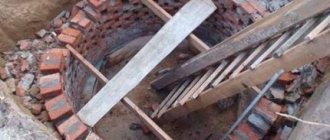
Installation of a collector well
Jheka did not immediately cut and deepen the rotary wells; he postponed it until the stage of landscaping the yard.
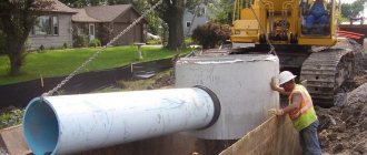
The collector well was assembled from two concrete rings with a diameter of 90 cm, a lid and a hatch. The rings were lowered into place using a manipulator.
Cost of drainage around the house
| Name of works | Cost, rub. |
| Drainage device, trench depth 0.5 m, per 1 m.p. | from 800 |
| Installation of inspection well D-315mm, pcs. | from 4 500 |
| Construction of a receiving well made of 3 reinforced concrete rings | from 27 000 |
| Installation of an automatic drainage pump (taking into account the laying of 5 m of electrical cable) | from 3 500 |
Helpful information:
calculation of rainwater drainage and wastewater
There is a misconception that the calculation of storm or rainwater drainage can be...
Operating experience
Jheka
During operation this fall, the drainage worked well. There is a lot of water, we have to pump it out twice a day. The water in the well collects above the drainage pipe.
But here it is worth noting that the storm drainage system has not yet been completed - through trays laid under the drainpipes, roof water is simply discharged into the ground, at a distance of about five meters from the house. According to the participants in the topic, with which the topicstarter is inclined to agree, it is these surface runoff that infiltrate and enter the drainage system, which leads to large volumes.
However, the system overwintered normally, and in the spring the site was drier, although some problems emerged - in the corners the soil swelled along with the blind area. Typically, this is the third winter for the blind area.
To avoid a recurrence, I first cut off the wells and insulated the covers with EPS (a layer of earth on top of about 8 cm) - it got better, but next spring the blind area was raised again. Therefore, in the summer I dug a trench parallel to the blind area in the corner areas and inserted EPS slabs also vertically. Considering that to this day Jheka has not reported any problems, most likely the system has been working properly for almost ten years.
Calculation and design
In order for the drainage installed on the land to function correctly and have the necessary throughput capacity, before starting work, you need to draw up a drainage system design.
This is technical documentation, which is compiled taking into account generally accepted requirements and SNiP standards.
Design begins with hydraulic drainage calculations. They will help determine the amount of material required for the work, as well as its characteristics.
During the calculations you need to determine:
- the degree of permeability of all rocks that make up the soil on the site, as well as the tendency of hard rocks present in this area to crack;
- indicators of rock resistance to leaching of mineral particles, which can provoke soil salinization;
- the presence of tectonic disturbances in the area, the quality of the rocks on it;
- the average amount of precipitation falling in a given climate zone over a certain period of time;
- level and composition of groundwater at the site;
- features of the location and activity of groundwater sources.
Hydraulic calculation of drainage
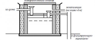
Of course, if we are talking about a private plot, then a drainage project in such cases is not always done; usually the standard system diagram is taken as a basis.
But, if there are special climatic or geological conditions here, the project is still needed.
Site drainage scheme
In addition to the above calculations, it is imperative to examine the topography of the site. Determine the location where the largest amount of water accumulates after rain or melting snow. This will help to correctly determine the slope of the drainage system elements and make it more efficient.
Now you can begin to design a drainage system for the site.
It will include:
Site drainage system design
- a schematic sketch of the laying of drainage pipes for the arrangement of deep and surface communications;
- design parameters of drainage pipes: length, cross-sectional diameter, slope, laying depth, as well as the distance between several drains;
- dimensions and location of other elements of the drainage system: connecting nodes, wells, water receivers;
- a list of materials that will be required to create an effective drainage system.
Landscape design for drainage
Having a project in hand, it will be easier to determine the required volume of material, as well as perform installation work.
In what cases is drainage used?
All drainage systems can be divided into several types according to their function:
- Wall drainage is designed to drain groundwater from the building and protect the site
- Drainage of the wetland area is carried out by more complex systems, which include a number of technological measures.
Wall drainage
The need to use one type or another can be determined by a number of indirect signs.
You need drainage if:
- In spring, the basement regularly floods. In this case, the organization of drainage should be carried out in conjunction with improving the waterproofing of the foundation.
The proximity of groundwater is also evidenced by the rising water level in drinking wells. The swampy condition of the site speaks for itself. With high humidity, there is also the presence of a large number of water-loving plants.
Calculation of drainage slope
Optimal pipe slope
You have calculated the place where the drainage will go and the depth of its installation. But for it to function properly, the pipe must lie at a slope from the top point towards the drain. The slope is calculated in the same way as for surface drainage and sewerage, 1–2 cm per 1 linear meter. To correctly calculate the slope of the entire highway, you can perform some calculations:
- From the top drainage point (usually located at the corner of the building), measure the length of the trenches dug along the 2 sides of the building that meet at the corner. For example, trenches are 9 meters long.
- Sum them up, and you get the total length of the trench - 18 m. Measure the distance from the building to the lowest drainage point, which is the drainage well.
- For example, let it be 10 m. Sum up two numbers: 18 + 10 = 28.
- You have the total distance from the top drainage point to the lowest drainage point, and it is 28 m.
- If 1% of the distance is taken to calculate the difference between two points, then it is 0.28 m. In other words, the difference in the location of the upper drainage point and the lower drainage point will be 28 cm.
Based on these calculations, slope your drainage.
Installation of a drainage well
To carry out drainage maintenance, inspection wells must be provided. Therefore, when calculating the deep drainage scheme, calculate the required number of wells and their location.
Main parts of a precast well
The drainage well should be located at the bend, but no further than 20 meters from the drainage bend, and on a flat area - every 30–40 meters. Place the drainage well at the lowest point, allowing for convenient drainage of water into a ravine or pumping with a drainage pump.
By correctly performing all the calculations for the construction of the drainage system, you can be confident in its quality and durability.
Monographs and brochures
Mukhamedzhanov Sh.Sh. – Use of collector and drainage water for irrigation in Uzbekistan (2019)
Usmanov A.U. — Use of mineralized water for irrigation (1987)
Yakubov Kh.E., Yakubov M.A., Yakubov Sh.Kh. — Collector-drainage flow of Central Asia and assessment of its use for irrigation (2011)
Articles
Azhibekova Z.A. — Use of collector and drainage waters for irrigation of agricultural land in the Kyrgyz Republic (2016)
Achoyan Zh.A., Kazaryan A.A. — Influence of the state of the drainage network on the module of groundwater flow (2003)
Vasiliev D.G., Chelakhov V.Ts., Domashenko Yu.E., Vasiliev S.M. — Environmental justification for the use of drainage runoff for irrigation of agricultural land (2019)
Vasiliev D.G., Chelakhov V.Ts., Domashenko Yu.E., Vasiliev S.M. — Assessment of the impact of treated drainage and waste water on the environment using the matrix method (2020)
Vasiliev S.M., Ariskina Yu.Yu., Domashenko Yu.E., Mityaeva L.A. — Justification of the effectiveness of the method of preparing groundwater for irrigation reclamation (2020)
Glazunova I.V., Peigen Ch. - Experience in the use of bioengineering structures in Russia and China and principles of calculation for drainage wastewater treatment (2011)
Domashenko Yu.E., Vlasov M.V., Vasiliev S.M., Matvienko A.O. — Environmental and economic justification for the use of wastewater in irrigation systems based on the dynamic programming method (2017)
Dukhovny V.A., Khodzhibaev N.N. — Problems of joint use of groundwater for irrigation in the Aral Sea basin
Evzhanov Kh.N. — Purification and reuse of collector and drainage water (2009)
Kapustyan A.S. — Justification of the volume and technical methods of using drainage water in local irrigation systems (2016)
Mamatov S., Umarov H. - The use of wastewater for irrigation is one of the ways to mitigate the shortage of irrigation water in the conditions of Uzbekistan (2010)
Matrasulov D., Kulmatov R.A. Modeling and improvement of methods for monitoring collector-drainage flow of the Republic of Uzbekistan (2007)
Musaev A.I. — Ecological and geochemical assessment of irrigation waters based on the hydrogen index (2010)
Nazarmamedov O. - Technology of bioengineering purification of drainage waters of Turkmenistan from toxic chemicals (2007)
Nikolaenko A.N., Kavokin A.A., Maksimenko V.P. — Modeling of recycling of collector and drainage waters for soil irrigation (2015)
Pulatov Ya.E., Aliev I.S. — Irrigation drainage and ways to use collector-drainage water (2002)
Ramazanov A., Fayzullaeva M. - Agroecological aspects of the use of mineralized water in the irrigated zone of Uzbekistan (2018)
Rejepov O., Gurdov A. - Use of collector-drainage waters for the development of desert-sandy soils in Turkmenistan (2007)
Serikbaeva E.B. — Environmentally safe irrigation regime for alfalfa when irrigated with wastewater (2007)
Seitkaziev A.S. — Methodological basis for the use of collector and drainage waters in conditions of water resource scarcity (2010)
Urinbaev S., Baraev F.A. — Mitigation of water resource shortages with the use of collector and drainage water for irrigation in the Republic of Uzbekistan (2015)
Usmanov A.U., Bekmuratov T.U. — Features of elements of irrigation technology when irrigating with underground water
Shirokova Yu.I. — Assessment of the quality of river and drainage waters of the republics of the Central Asian region for irrigation purposes (2002)
Emikh V.N. — Drainage in groundwater flow through a curtain (2002)
Regulatory, methodological and reference information
Requirements for irrigation and drainage standards when using mineralized water for irrigation (1989)
Advisory Documents and Guides
Recommendations for the assessment and possibility of using drainage water for irrigation in the Khorezm region (1992)
Guidelines for the use of drainage water for irrigation of agricultural crops and leaching of saline lands (1986)
Recommendations for the assessment and possibility of using collector and drainage water for irrigation of the Fergana region / Sh.Sh. Mukhamedzhanov (1989)
Recommendations for the assessment and possibility of using collector and drainage water for irrigation of agricultural crops in the Andijan region / Sh.Sh. Mukhamedzhanov (1990)
Recommendations for the assessment and possibility of using collector and drainage water for irrigation of agricultural crops in the Namangan region / Sh.Sh. Mukhamedzhanov (1990)
Drainage of water from the roof
The roof drain material is varied: steel, copper, polymer-coated steel, aluminum, etc. Plastic is especially popular. It is economical, resistant to damage, is a sound-insulating material, airtight, and light in weight and installation.
To properly design a roof drain you will need:
- Metal bracket;
- Hairpin with a special nut;
- Adjustable mount;
- Gutter bracket;
- Tip;
- Connecting coupling;
- Knee;
- Funnel plug;
- Gutter plug;
- Corner element;
- Funnel;
- Gutter connector;
- Gutter;
- Drain pipe.
The quantity and type of each element depends on the perimeter of the roof and the amount of pumped liquid, because too powerful a drainage system is irrational from the point of view of financial costs, and a weak one will not cope with the task. It is necessary to find the best option. The figure shows the required dimensions typical for central Russia.
On a note! To reduce the cost of purchasing consumables, you can make gutters yourself. You can make concrete elements at home using special pouring molds.