Sewerage and water supply system design
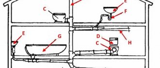
The system design includes the location of sewerage nodes and information for installers. This is necessary for convenient and correct reading of the project. Therefore, the symbols for sewerage according to GOST are alphanumeric.
The project includes:
- well table data;
- pipe layout plan for wastewater disposal;
- specification.
The drawing also shows the information necessary for installing the sewer system.
Future sewer plan
Only with a responsible approach to design will the systems work without breakdowns and will not create problems for residents. It will not be possible to complete such a task without knowledge and experience on your own, so it is better to entrust the work to a designer.
Types of seams according to GOST standards (squares 2 and 3 examples)
Possible methods of connecting two elements are closely discussed in GOSTs 14771-76 and 5264-80. There are the following types of welding joints:
- C – butt weld . The two elements being connected are in the same plane and at the same level. They are connected to each other by adjacent ends. This is one of the most popular connection options. Its peculiarity lies in the fact that the mechanical characteristics of the weld are very high, and the appearance of the finished structure is aesthetic. Along with the positive aspects, there are also negative ones. This type of connection remains technically difficult. It can only be performed qualitatively by experienced specialists.
- T – tee seam . This implies a connection of two elements located at an angle of 90 degrees relative to each other, and the junction has a T-shaped configuration. This is the most rigid connection option of all those considered. Therefore, it is not used in cases where some elasticity is important for the finished structure.
- N – lap seam . Two workpieces are located parallel, but not in the same plane. They are in contact with some overlap of the plane. A fairly strong and reliable connection method, but in terms of rigidity it is inferior to the T-type version.
- U – fillet weld . The ends of two workpieces are positioned at an angle of 90 degrees. The ends melt, resulting in a fairly strong and rigid connection.
- O – special types . This designates all other options for welding workpieces that are not described in the standard.
Both GOST standards mentioned at the beginning of the section have common features and overlap with each other. For manual arc connection according to GOST 5264-80:
- C1 – C40 butt;
- U1 – U10 corner;
- H1 – H2 overlap;
- T1 – T9 tee.
Performing welding work in an inert environment in accordance with GOST 14771-76:
- U1 – U10 corner;
- C1 – C27 butt;
- H1 – H4 overlap;
- T1 – T10 tee.
The example above contains the numbers just discussed. The second square contains information on the standard used - 14771-76. The third square describes the connection method - double-sided T-joint without beveled edges.
Symbols in the drawings
Before designing a residential building, nuances that may affect the operation of the plumbing system are determined. You need to find out in advance whether there is a centralized network near the construction of a residential building and whether pressure drops can occur due to it.
If there is no network, a local water supply system is created. In this case, a storage tank is installed.
Project stages:
- Calculation of the maximum load on the supply pipeline in the house (depends on the number of water intake points in the house and on the site).
- Selection of options for restoring water supply standards when pressure in networks decreases.
- Selecting a device according to a suitable scheme.
To accurately locate the water supply symbols on the drawing, it is necessary to establish what elements the system consists of. The price and quality of materials for fittings and plumbing fixtures can be anything. This does not affect the operation of the system in any way.
The difference between the drawing according to ESKD and GOST
No difference! ESKD is a unified system of design documentation. It contains state standards with norms according to which design drawings are developed, executed and used. Such state standards are abbreviated as GOSTs.
Students often confuse ESKD and GOST standards. ESKD is a general system, and GOSTs contain general rules for the preparation of drawings, diagrams and accompanying documents for all industries. Their compliance is mandatory for enterprises, organizations, and educational institutions.
Sewerage markings K1, K2, K3
Each drawing indicates o and the number 1,2 or 3. The marking depends on the purpose of the sewerage system.
For a household system, “K1” is used, for a rainwater system – “K2”, for an industrial system – “K3”.
You cannot put symbols in the drawing that are not specified in the regulatory documents GOST 21.205-93 and SNiP 2.04.03-85 (SP 32.13330.2012). This is necessary so that workers can find the desired designation and correctly complete the work on the project.
The use of symbols according to the regulations allows you to achieve the normal functioning of the sewerage system for a long time. Owners of houses or apartments will not worry about problems in the utility network.
Technical drawing
Popular
Drawing Basics
Construction
Mechanical Engineering
The slope of straight line BC relative to straight line AB (Fig. 57, a) is the ratio:
i=AC/AB=tga
Taper is the ratio of the difference in diameters of two cross sections of a cone to the distance between them (Fig. 57, b)
k=(Dd)/l=2tga
k = 2i
The slope and taper can be indicated: a) in degrees; b) a simple fraction, in the form of a ratio of two numbers or a decimal; c) as a percentage.
For example: taper expressed in degrees - 11°25'16"; ratio - 1:5; fraction -0.2; in percentage - 20%, and accordingly, the slope in degrees is 5 ° 42'38 "; ratio - 1:10; fraction—0.1; as a percentage - 10%.
For cones used in mechanical engineering, OCT/BKC 7652 establishes the following series of normal tapers - 1:3; 15; 18; 1 : 10; 1:15; 1:20; 1:30; 1:50; 1:100; 1:200, as well as 30, 45, 60, 75, 90 and 120°.
In special cases, tapers of 1:1.5 are also allowed; 1:7; 1:12 and 110°.
If it is required to draw a straight line through point A lying on straight line AB (Fig. 57, c) with a slope i=l:n relative to AB, n arbitrary units must be set aside from point A in the direction of this straight line; at the end of the resulting segment AB, restore the perpendicular EC with a length of one same unit. The hypotenuse AC of the constructed right triangle determines the desired line.
To draw a straight line of a given slope l:n through a point M that does not lie on a given straight line AB, you can proceed in two ways (Fig. 58):
1) construct a right triangle KLN (or KLN1) to the side with the ratio of legs l:n, and leg KL ll AB; then, through point M, draw the desired straight line MD (or MD1) parallel to the hypotenuse of the auxiliary triangle KN (or LN1);
2) lower the perpendicular ME from point M to line AB and take it as one. In the direction of straight line AB to the left or to the right from point E, set aside n similar segments; the hypotenuses DM or MD1 of the right triangles constructed in this way are the required straight lines.
Storm drainage design
To design a stormwater system, you need to perform the following calculations:
- Select the type of drainage: self-draining or forced. In the first case, it is necessary to calculate the slope of the pipe for normal wastewater drainage and indicate the marking.
- Determine the location of sanitary facilities in the room and options for connecting them to the sewer system.
- Select the type of sewerage drainage: centralized or autonomous. The first involves the removal of waste through the village-wide sewerage system. In the second case, disposal is carried out through a cesspool.
8.Evaluate the coated internal drain
The internal drainage system is designed to drain atmospheric precipitation through a network of pipelines through the building into a storm drain (city drain). The internal drain consists of drainage funnels, pipelines, outlets, devices for cleaning and inspecting the network through audits.
Drainage funnels are installed in low areas of roofs, one or two per section of a residential building, in tray roofing panels. The number of funnels on the roofs of other buildings is calculated from the condition that there is one funnel per 250...500 m2 of roof area. A minimum slope of 0.025 is provided to the funnels due to a constructive solution or a screed made of cement-sand mortar.
Internal drainage risers are installed from cast iron free-flow pipes in buildings up to three floors high, from cast iron pressure pipes - in buildings over three floors. Drainage risers can also be made of steel, asbestos-cement and plastic pipes with appropriate justification. The minimum diameter of drainage pipes is 50 mm. They are laid along building structures, hidden or open.
Regulatory acts
SP 32.13330.2012 specifies the requirements for calculations, pumps, manholes, air duct stations, and sewers.
In addition, general positions, laying depth, design speeds, connections, laying slope, turns, fillings and minimum pipe sizes are taken into account.
The rules contain links to regulatory documents that are necessary for the design of a water supply and sewerage system.
The rules include the technological section, dispatching, standards for electrical appliances, space-planning solutions, automation system, technology control, control system, standards for sewerage in special climatic conditions.
Pipeline
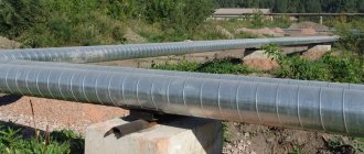
In modern technology, pipelines are devices that are intended for transporting a variety of liquid, gaseous and granular media. The main components of pipeline systems are: straight pipes that are tightly connected to each other; suspensions and supports; control and measuring equipment; shut-off and control devices; fasteners; seals and gaskets; automation means.
In addition, the elements of pipeline systems also include the materials necessary to provide effective protection of all the above components from the harmful effects of low and high temperatures, as well as from electrochemical corrosion.
The locations of the elements of pipeline systems are their branches, turns, as well as transitions to another diameter. They serve to ensure a long service life of the system as a whole, as well as the tightness of the entire structure. Practice shows that without such elements as bends, tees and transitions, practically no pipeline system is currently implemented.
Utility networks during topography
The main task of surveyors when conducting a survey is to determine the location and plotting of internal and external utility networks and linear elements on a topographic map.
The object of search work and topographic surveys can be underground or above-ground communications. If it is necessary to update the plan taking into account the terrain or draw up new documentation, you need to study materials from the archive and the existing geology of the site.
When conducting topographic surveys, it is important to agree on the nuances and obtain permits indicating diagrams, technical data, designed plans of linear structures, and route profiles.
Then data is collected using a tacheometer and a GPS device and desk processing of the information is performed. On the topographic plan, the necessary relief features, sewerage and water supply elements are noted.
Atmospheric precipitation removal
To prevent premature subsidence of buildings and cracking of walls, effective rainwater drainage system K2 is installed.
Its task is to collect, purify and remove atmospheric moisture. Often K2 is structurally combined with the drainage system. Rules for installing sewerage systems
Storm sewer consists of above-ground and underground parts. On the surface, the system consists of inlet funnels, outlet pipes and open gutters. Filters that purify rain and melt water from solid contaminants can be located both superficially (usually) and in the underground part of the drainage network.
If there is a communal storm drainage system, atmospheric precipitation is collected centrally and, after being cleared of mechanical impurities, is discharged into reservoirs. In suburban areas it is also often possible to drain atmospheric moisture into nearby natural reservoirs. If this is not the case, special wells are constructed into which surface groundwater from the drainage system is also discharged.
External and internal diameter of pipes and pipeline fittings
DN - Nominal diameter.
Used as a characteristic of connected parts such as: pipeline fittings, fittings, connections for various types of pipelines.
Nominal diameter (rounded internal) does not mean the exact size in millimeters and is approximately equal to the value of the internal diameter of the connected pipeline in millimeters (Defined in GOST 28338-89, corresponds to ISO 6708-80).
The parameter was introduced to reduce the standard sizes of fittings, pipelines and various connecting parts; the concept of nominal diameter was adopted.
According to GOST 28338-89, it must be designated by the letters DN and a numerical value, which is selected from the standard series.
Previously the designation was used: Dy – Conditional diameter
All GOSTs mentioned in the text at the time of writing this article on 02/01/2018 are valid
Indication of the nominal diameter depending on the type of pipe
When indicating the nominal diameter for pipeline fittings, everything is extremely simple. The rounded internal diameter is indicated, for example, like this: DN20, but sometimes an outdated designation can be found: DN20, or Dy20, according to the previously valid CMEA 254-76.
But with the indication for different types of metal and plastic pipes, not everything is so simple, and confusion often occurs due to incorrect indication or uncertainty as to what diameter is indicated, external or internal (nominal diameter).
And the question arises, how is the pipe diameter correctly indicated? The following are examples of correct designations for some types of pipelines.
Designation of water and gas pipe (VGP pipe)
Water and gas pipes (WGP) include metal welded products made of steel in accordance with GOST 1050 and GOST 380, as well as other approved regulations. Applicable:
- In building heating systems;
- Various types of water pipelines;
- In the designs of gas pipeline systems and gas pipelines;
Example notation
Steel pipe manufactured in accordance with GOST 3262-75, with a nominal bore of 32 millimeters and a wall thickness of 3.2 millimeters.
The same thing only with the clutch.
Steel VGP with thread, zinc coating, cut to length. And so on.
Designation of electric-welded straight-seam pipes
Straight-seam electric welded steels are made from low-alloy or carbon steels. Used for the manufacture of pipelines for various applications.
Example notation
Steel pipe, produced in accordance with GOST 10704-91, with an outer diameter of 70.0 millimeters, a wall thickness of 4.0 millimeters, measured length (5000 mm), class II (manufacturing accuracy along the length), made of steel “StZsp”, produced in accordance with group “B” of GOST 10705- 80.
Specifying the diameter of seamless steel pipes
Seamless steel pipes are made from alloy or carbon steels. The absence of seams increases the resistance of the pipeline to various physical influences, such as operating temperature and nominal pressure.
Example notation
Steel pipe produced in accordance with GOST 32528-2013, with an outer diameter of 60.0 millimeters, a wall thickness of 4.0 millimeters, measured length (6000 mm), increased manufacturing accuracy, grade 40X steel, produced according to group “B”.
Unmeasured length, produced in accordance with GOST 32528-2013, with an outer diameter of 95.0 millimeters and an internal diameter of 76.0 millimeters, steel grade 10, produced according to group “B”.
Indication of plastic pipe diameters
Plastic pipes and various fittings are made from the following types of thermoplastics:
They are used for the manufacture of heating pipes, hot and cold water pipelines in accordance with GOST 32415-2013.
Example of designation of plastic pipes and fittings
Manufactured from uPVC, with a nominal outside diameter of 25.0 millimeters, a nominal wall thickness of 2.3 millimeters, and a pressure rating of PN25.
Symbol for plastic fittings:
Coupling made of PVC-U for connecting pipelines with DN 63.0 mm, complies with SDR 13.6, nominal design pressure PN16.
