Here you will learn:
- Purpose of the hydraulic accumulator
- Hydraulic accumulator device
- Principle of operation
- Types of hydraulic tanks
- Criteria for selecting a suitable hydraulic tank
- Calculation of the optimal volume of the hydraulic tank
- A few words about the connection diagram
- Malfunctions
- Recommendations for use
The design of a hydraulic accumulator with a replaceable membrane looks simple. This is a metal tank with an elastic membrane of a spherical or pear shape.
Purpose of the hydraulic accumulator
A hydraulic accumulator (in other words, a membrane tank, hydraulic tank) is used to maintain stable pressure in the water supply system, protects the water pump from premature wear due to frequent activation, and protects the water supply system from possible water hammer. When the power goes out, thanks to the hydraulic accumulator, you will always have a small supply of water.
Here are the main functions that a hydraulic accumulator performs in a water supply system:
- Protecting the pump from premature wear. Thanks to the water reserve in the membrane tank, when you open the water tap, the pump will only turn on if the water supply in the tank runs out. Any pump has a certain rate of starts per hour, therefore, thanks to the hydraulic accumulator, the pump will have a reserve of unused starts, which will increase its service life.
- Maintaining constant pressure in the water supply system, protecting against changes in water pressure. Due to pressure changes, when several taps are turned on at the same time, sharp fluctuations in water temperature occur, for example in the shower and in the kitchen. The hydraulic accumulator successfully copes with such unpleasant situations.
- Protection against water hammer, which can occur when the pump is turned on, and can seriously damage the pipeline.
- Maintaining a supply of water in the system, which allows you to use water even during a power outage, which happens quite often these days. This function is especially valuable in country houses.
Rules for starting and setting up equipment
Before starting the pumping equipment for the first time, it is first necessary to prepare the hydraulic accumulator, since the stability of the entire water supply system depends on the correctly selected pressure in it. A high pressure in the tank will provoke frequent switching on and off of the unit, which will not have the best effect on its durability. If there is low pressure in the air chamber of the tank, this will lead to excessive stretching of the rubber bulb with water, and it will fail.
The hydraulic tank is prepared as follows. Before pumping air into the tank, make sure that the bulb inside it is empty. Next, check the pressure in the tank with a car pressure gauge. Typically, new tanks are filled with air at the factory. Hydraulic tanks up to 25 l should have a pressure in the range of 1.4-1.7 bar. In containers of 50-100 liters, the air pressure should be in the range from 1.7 to 1.9 bar.
Advice! If the pressure gauge readings are lower than recommended, then you should pump air into the tank using a car pump and adjust it, referring to the pressure gauge readings.
First launch of the station
To correctly start the pumping station for the first time, perform the following steps step by step.
- Unscrew the plug that closes the water hole located on the unit body. Some devices may have a valve instead of a plug. It should be opened.
- Next, fill the suction pipe and pump with water. Stop pouring liquid when it begins to flow out of the fill hole.
- When the suction pipe is full, close the hole with a plug (close the valve)
- Connect the station to the power supply and turn it on.
- To remove remaining air from the equipment, open the tap at the water intake point closest to the pump.
- Let the unit run for 2-3 minutes. During this time, water should flow from the tap. If this does not happen, then turn off the pump and refill the water, and then start the pumping station.
https://youtube.com/watch?v=6OYksymY7vY
Setting up automation
After a successful launch, you need to check and configure the operation of the automation. The new pressure switch has factory settings for the upper and lower pressure thresholds, upon reaching which it turns the pump on or off. Sometimes it becomes necessary to change these values by setting them to the desired on-off pressure.
Automatic adjustment occurs as follows.
- Turn off the unit and drain the water from the accumulator.
- Remove the cover from the pressure switch.
- Next, you should start the pump so that water begins to flow into the hydraulic tank.
- When turning off the device, write down the pressure gauge readings - this will be the value of the upper shutdown threshold.
- After this, open the tap at the most distant or highest point of water intake. As water flows out of it, the pressure in the system will begin to decrease, and the relay will turn on the pump. The pressure gauge readings at this moment will indicate the lower switching threshold. Record this value and find the difference between the upper and lower threshold.
Normally, the switching pressure should be 2.7 bar, and the switching pressure should be 1.3 bar. Accordingly, the pressure difference is 1.4 bar. If the resulting figure is 1.4 bar, then nothing needs to be changed. If the pressure is too low, the unit will turn on frequently, which will cause premature wear of its components. If it is too high, the pump will operate in a more gentle mode, but the difference in pressure will be obvious: it will be unstable.
Advice! To increase the pressure difference, tighten the nut on the small spring. To reduce the difference, the nut is loosened.
When checking the operation of the relay, pay attention to the pressure with which water flows from the tap. If the pressure is weak, you will need to adjust the pressure
In this case, the pressure in the system should be higher. To raise it, turn off the device and slightly tighten the nut that presses the large spring of the pressure switch. To reduce the pressure, the nut must be loosened.
Hydraulic accumulator device
The design of a standard hydraulic accumulator with a replaceable membrane (the most common type) is quite simple. Inside the accumulator there is an elastic membrane of a spherical or pear shape.
In operating mode, there is water inside the membrane, and between the walls of the tank and the membrane there is pre-injected air or other gas under pressure (the pre-injection value is indicated on the label). Thus, water does not come into contact with the walls of the accumulator, but only with the membrane, which is made of material suitable for contact with drinking water.
The membrane neck remains outside the accumulator housing and is securely attached to it by a steel removable flange using screws. Thus, the membrane is removable and can be replaced with a new one without much labor.
All hydraulic accumulators have a nipple in their design (like in a car wheel), which is directly connected to the air cavity of the tank. Through this nipple, you can regulate the air pressure inside the tank using a conventional air pump or compressor.
The nipple is located under a protective plastic cap, which can be easily unscrewed by hand.
It is important to note that many manufacturers have membranes in hydraulic accumulators with a volume of 100 liters and above attached not only from the bottom (via a flange), but also from the top. Through the hole in the upper part of the membrane (yes, in addition to the neck, the membrane will have another hole in the upper part) passes a special hollow rod, with a sealing element at one end and a thread at the other. The threaded end is brought out of the tank and is attracted to the latter by a nut. In fact, the part brought out is a threaded fitting. This threaded fitting can simply be plugged, or a pressure switch and/or pressure gauge can be installed on it.
In this case, the hydraulic accumulator (as well as the membrane to it) will be called pass-through.
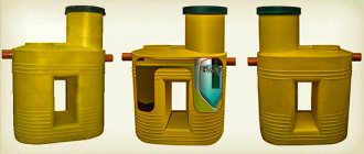
Hydraulic accumulators come in vertical and horizontal versions. Vertical tanks are installed on legs, while horizontal tanks are mounted on feet and have a platform for installing additional equipment. Equipment (pump, control cabinet, etc.). The fundamental point for choosing a layout is the specific installation location.
When installed on the floor, a vertical tank will be more compact, but if the tank needs to be hung on the wall or there are height restrictions, choose a horizontal model.
How to check the pressure in the accumulator
To measure pressure you need:
- unscrew the cap that closes the fitting with the spool located on the tank body;
- connect the pressure gauge to the spool (you can use an electronic or automobile pressure gauge), take the reading and compare it with the calculated value;
- if the pressure level decreases, pump up the compressor to the optimal value;
- To reduce pressure, bleed air.
If adjustment is carried out before the hydraulic tank is included in the system, it must be left for a day. After this time, after a control measurement, the device is installed.
Principle of operation
Radial membranes (in the form of a plate) are used mainly in gyroaccumulators for heating systems. For water supply, a rubber bulb is usually installed inside. How does such a system work? As long as there is only air inside, the pressure inside is standard - the one that was set at the factory (1.5 atm) or that you set yourself. The pump turns on, begins to pump water into the tank, and the pear begins to increase in size. Water gradually fills an increasingly larger volume, increasingly compressing the air that is located between the wall of the tank and the membrane. When a certain pressure is reached (usually for one-story houses it is 2.8 - 3 atm), the pump is turned off, and the pressure in the system stabilizes. When you open a tap or other water flow, it comes from the accumulator. It flows until the pressure in the tank drops below a certain level (usually about 1.6-1.8 atm). After which the pump turns on, the cycle repeats again.
The operating principle of a gyroaccumulator with a pear-shaped membrane
If the flow rate is large and constant - you are filling a bathtub, for example - the pump pumps water in transit, without pumping it into the tank. The tank begins to fill after all the taps are closed.
A water pressure switch is responsible for turning the pump on and off at a certain pressure. In most hydraulic accumulator piping schemes, this device is present - such a system operates in optimal mode. We’ll look at connecting the hydraulic accumulator a little lower, but for now let’s talk about the tank itself and its parameters.
Purchase and price
To avoid becoming a victim of scammers duplicating products from well-known brands, you should buy water supply systems in the store of one of the large retail chains, which almost always work directly with the manufacturer.
In addition to the mentioned Reflex, users speak well of such manufacturers as Wester, Zilmet, Varem, AquaSystem, etc. The cost of these devices varies from 28 (Chinese-made tanks, characterized by low quality) to 200 dollars.
Hydraulic accumulator after installation
Types of hydraulic tanks
There are vertical and horizontal devices, they are installed in different ways. Typically, tanks with a capacity of up to 50 liters are placed horizontally, and larger ones - vertically, so as not to take up much space. This does not affect efficiency. You can choose a model that will be more convenient to use and suitable for the place where it will be installed.
The total volume of the hydraulic tank and the amount of water it can hold are different indicators. The container is selected depending on the characteristics of the plumbing system
In vertical and horizontal models, a nipple - an air valve - is provided to remove air from the part into which air or gas is pumped. It's very easy to use.
It is located on all types of hydraulic tanks on the side opposite to the installation of the flange intended for connecting equipment to the water supply.
Membrane tanks with a red body are intended for hot water supply systems or heating. They must be used strictly for their intended purpose.
The color of the container is usually blue or blue, in contrast to the red expansion tanks for heating. They are not interchangeable; different materials are used to make the membrane. Food-grade rubber is used in “cold” hydraulic tanks.
In addition, blue accumulators can withstand higher pressure than heating and hot water devices. You cannot use such containers for other purposes; they will quickly fail.
In vertically oriented HAs, water is supplied from below, and excess air is removed, if necessary, from above, bleeding it through the nipple. In horizontal versions, both water supply and air bleed are done from the side.
The threaded connection for connecting to the water supply is always the same size, it is 1 1/2 inches. The thread for connecting the membrane can be internal or external. Their dimensions are also unified, the internal thread is standard 1/2 inch, the external thread is 3/4 inch. This is an important point, since for a reliable connection it is necessary that the dimensions of the nozzle and the water pipe match.
If you plan to organize an independent water supply system, you need to know how a conventional water accumulator works. You should immediately decide on options for connecting to the water supply and methods for removing air if the pressure exceeds the standard value, as well as connection diagrams to the system.
Imported GA models look very presentable, but they are not always suitable for use in local conditions. Before purchasing such a device, you should read reviews
It should be remembered that they were initially designed to suit the conditions of the country where they were produced, and they do not always coincide with local realities. Operating conditions may be too difficult for Western models, so it makes sense to look for an option from a domestic manufacturer, which may be more attractive in cost.
How to determine damage to the accumulator
As in a water supply system, a hydraulic accumulator has its own service life. So, for built-in tanks it is determined by the service life of the heating boiler, and a free-standing tank made of ferrous metal usually withstands a 5-6 year period of operation. When filling the system volume with antifreeze, you must carefully study the manufacturer's recommendations to make sure that the material will not react with the antifreeze chemical.
The first sign that the accumulator has failed is a sharp drop in pressure in the system. The fact is that the bottleneck of the accumulator is the membrane. Despite its elasticity and strength, during operation, particles of debris from the internal volume of batteries, pipes, shut-off valves enter its cavity, and insoluble sediments from the water itself often accumulate here. And then, during operation of the membrane, these particles play the role of an abrasive, gradually rubbing the rubber. When the membrane walls break, air from the air chamber penetrates into the heating system and is removed through the air vent, and the freed volume is filled with coolant. In this case, no visible coolant leaks are detected in the room.
If you do not pay attention to the sharp decrease in pressure in the system and simply restore the required fluid pressure, then despite the breakdown of the hydraulic accumulator, the system will continue to operate. But at the first emergency situation, the scale of the accident will be much larger
To systematically monitor the condition of the membrane, it is recommended to periodically check the pressure in the accumulator using a conventional pressure gauge from a road car kit.
To be sure that the equipment is working properly, it is recommended to press the nipple and release a little air 1-2 times every 6 months. A rapid whistling stream of air will indicate that the tank is leaking. But if you hear a faint hissing sound or water drips out instead of air, then you need to sound the alarm - the membrane will most likely be damaged and the device will need to be repaired.
The second common problem when operating hydraulic accumulators is the loss of housing tightness. Unlike water supply system receivers, this problem is relatively rare, but it cannot be discounted. Such damage occurs as a result of improper installation or as a result of improper repair of the device. The tank body is usually made of steel or iron sheet by stamping. The outer part of the tank is painted to protect it from corrosion, but the inside is usually left without an additional protective layer. During operation, pockets of corrosion form on the inner wall of the air compartment, which causes a hole to form over time, and the air simply escapes. It is easy to determine such a malfunction - you need to start deflating the air with a few presses; if you cannot hear a characteristic whistle when pressing, then you need to look for damage to the housing.
Another common type of failure is a spool valve malfunction. This usually happens when setting up the device, when there is a need to constantly pump it up with a pump and check the pressure with a pressure gauge. If the spool is damaged, the pressure usually drops gradually, and on the boiler pressure gauge you can notice that the pressure does not decrease immediately, but over time, in small portions. It should be noted that it decreases, and does not jump in a certain amplitude. Directly on the tank, you can check whether the valve is working or not by applying a small amount of soap solution to it. If the solution does not change its state, then the problem is not with the valve. And if the escaping air blows up soap bubbles, even small ones, then the valve core needs to be replaced. The easiest way to buy it is at an auto store or sporting goods store; the core in the valve is identical to that used in car and bicycle tires.
Criteria for selecting a suitable hydraulic tank
When choosing a specific hydraulic accumulator, you must be guided by the following criteria:
- Number of consumers
- Working fluid temperature
- Cost of equipment
- When using a hydraulic tank to compensate for changes in coolant pressure in a closed heating system, volumes from 6 to 25 liters are sufficient (the specific figure depends on the size of the heating system itself). The remaining characteristics of the hydraulic tank allow it to confidently work in the same system with heating devices (for example, the maximum pressure that the boiler heat exchanger can withstand is 2-5 atmospheres, and for the hydraulic tank - 9-12 atm)
Calculation of the optimal volume of the hydraulic tank
A correctly selected hydraulic tank volume will allow:
- ensure sufficient water consumption,
- optimal use of pumping equipment,
- extend the service life of the drive and system elements.
There are several ways to select a hydraulic accumulator for water supply systems and calculate the required storage volume.
Italian engineers have developed a calculation method UNI 8192. Selection is carried out according to three parameters: maximum water flow, the number of permissible pump starts per hour and the water supply height.
If the need for water supply is small, for example, for a family of 2-3 people living in a one-story house, the volume of the hydraulic tank can not be calculated. A 24-liter container will be enough.
For houses with more floors and with a considerable number of water consumption points, a calculation should be made.
The required hydraulic tank size can be selected only based on calculations
It is carried out according to the scheme:
- The tables determine the total coefficients of water consumption depending on the equipment used.
- The maximum water flow is calculated. For example, when a shower, cistern and faucet work together in the kitchen, this figure will be 30 l/min (Qmax).
- The estimated number of pump starts per hour (for comfortable operation) is taken as a=15. With more intensive work, the hydraulic tank membrane oscillates too frequently, which leads to its premature destruction. In addition, the pump’s performance does not make it possible to completely fill the reservoir with water. During continuous operation, the pump overheats and fails faster.
- The next important value is the maximum and minimum pressure for the relay to operate. For two-story houses these values are 3 bar and 1.5 bar, respectively (Pmax and Pmin). The initial gas pressure in the setting P0=1.3 bar is included in the calculation.
- The required volume is determined by the formula: V=16.5 x Qmax x Pmax x Pmin /(ax (Pmax-Pmin)x P0)=16.5x30x3x1.5/(15x(3-1.5)x1.3)=76 l.
The closest in value is a tank with a volume of 80 liters.
A hydraulic accumulator for water supply systems with such a capacity will allow meeting the water supply needs of residents of a 2-story building with three water collection points operating simultaneously.
How to correctly calculate and select a hydraulic accumulator can be seen in the video:
Do you need extra capacity?
The additional volume of water stored in the hydraulic tank does not affect its operation. The main function of the unit is to maintain pressure in the water supply network.
If a significant supply of water is needed, it is easier and much cheaper to integrate a plastic reserve tank into the system. Therefore, when selecting equipment, it makes no sense to purchase a hydraulic accumulator with a reserve.
If the need for water supply increases, for example, with an increase in the number of residents or the number of household appliances consuming water, you can additionally install another small-volume hydraulic tank. Their performance is cumulative. The installation location of the additional hydraulic tank does not play an important role.
If necessary, several hydraulic tanks can be installed in the system
How to connect a hydraulic accumulator for heating, calculation rules and diagram
When selecting equipment, the characteristics of the system are taken into account.
For installation in a water supply system, a tank with a membrane designed for drinking or industrial water is selected; for installation in a heating or hot water supply system, the membrane must correspond to the intended purpose. In hot water supply and heating, the water temperature reaches 80 and even 120 degrees, so equipment is selected taking into account the effects of high temperatures. To be installed in a heating system, the tank must withstand pressure up to 4 atmospheres, and the temperature must not be lower than 120 degrees. For water supply, the maximum temperature is estimated at 80 degrees, and the pressure that the tank must withstand must be at least 12 atmospheres. The selection of a device that meets the parameters of the heating system can be calculated using the formula for determining the volume of a hydraulic accumulator:
V = (VL x E) / D
Where D = (PV – PS) / (PV + 1).
PV is an indicator of the maximum operating pressure in the system, and PS is the air pressure in the membrane tank. For small private houses and systems installed in apartments, the PV indicator is taken to be 2.5 bar. As for PS, it is customary to take into account the constant pressure in the circuit, which is assumed to be 0.5 bar or equal to 5 m.
As an example, we can suggest calculating the volume of a tank for a house heating system of 100 square meters. meters. A 20 kW boiler is installed in the room.
First, the volume of coolant in the heating circuit is determined:
VL= (20x15)=300 liters.
Where 20 is the power of the heating boiler, and 15 liters is the specific volume of coolant for each kilowatt of power of the heating device.
The next step is to calculate the efficiency of the accumulator using the formula:
D = (PV – PS) / (PV + 1).
In which, PV = 2.5 bar and PS = 0.5 bar
As a result of performing actions:
D = (2.5 – 0.5) / (2.5 + 1) = 0.57
The last stage is the calculation of the directly required volume of the expansion tank.
V = 300 x 0.04 / 0.57 = 21.05 l where 0.04 is the expansion coefficient of water.
Thus, for a heating system with a 20 kW heating boiler and a total volume of coolant for a heated room of 100 square meters, a tank with a volume of 21-25 liters is sufficient
True, given the fact that manufacturers mainly offer consumers tanks of a standard volume, when choosing, it is recommended to pay attention to installations with a volume slightly larger than that obtained in the calculation. If you choose a tank of a smaller volume, then there is a high probability that the operating pressure of this device will be less than required, which can lead to an emergency situation
When determining the position of the tank during its installation, the fact that the accumulator itself has a housing as a supporting structure is taken into account. This is especially true for devices with a volume of up to 50 liters.
In a professional environment, it is generally accepted that small volume tanks up to 30 liters are wall-mounted, but larger volume tanks are better placed in a floor-mounted version. When installing these devices, it is recommended to further strengthen the fastening with brackets or clamps. For large-volume tanks, it is recommended not to reinvent the wheel, but to install them according to the recommendations of equipment manufacturers - using standard legs and structures on the body. The supply of pipes to the tank nozzle must be done along the shortest route, with a minimum number of bends and turns. And it is recommended to make the outlet itself as short as possible so that the device operates efficiently.
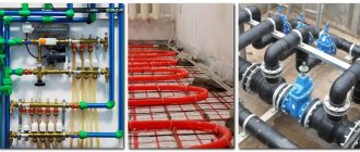
A few words about the connection diagram
Membrane accumulators are installed between the pump and the internal water supply. Since there is only one hole in the container, a crosspiece is used for connection, to which three elements are in turn connected:
- Pressure switch through which the pump is connected to electricity;
- The pump itself;
- A water pipe connecting the storage tank to the internal water supply.
The maximum pressure in the system should be 2.5-3 bar; when it is reached, the pump should turn off. The minimum is usually 1.5-1.8 bar.
Therefore, installing the container is not difficult even for beginners. The main thing is to ensure the tightness of all connections.
In addition, you need to configure the relay by setting the minimum and maximum pressure. Detailed information about this procedure is contained in the operating instructions for the device.
Installation stages
1. First you need to cut off the valve from the top of the cylinder. Carefully align the edges of the cut.
2. Thoroughly clean the inner walls down to metal.
3. Treat the cleaned surface with a phosphate converter and, after drying, with a primer.
4. Weld a counterflange ring into the resulting hole after cutting the valve. The ring must be made of sheet steel (5-6 mm), and the parameters must correspond to the parameters of the accumulator flange for connection to the system.
5. Polish the junction of the ring and the walls of the cylinder until it shines.
6. Insert a car nipple into the bottom of the gas cylinder.
7. Coat the inner walls of the cylinder with epoxy varnish. Allow to dry thoroughly for 7-10 days.
8. Place the rubber casing inside the cylinder.
9. Install the flange.
The homemade battery is ready. All that remains is to pump in air and check the flange seal for leaks. Next, the pressure is set using the pressure gauge, and the equipment is connected to the water supply. It is advisable to equip such a system with a pressure switch to make adjustments.
Malfunctions
Most often, hydraulic accumulators fail for the following reasons:
- too frequent starting/shutdown of the pump;
- valve leakage;
- water pressure at inlet/outlet is too low.
Before identifying the reason behind the weakening of pressure, it is necessary to determine what exact pressure should be in the station’s hydraulic tank.
In this case, problems may be as follows:
- incorrect pressure;
- damage or deformation of the membrane part or housing;
- relay failure.
You can deal with the difficulties that have arisen in the following ways:
- Injection of pressure in case of its decline;
- restoration of damaged membrane;
- restoration of damaged hull;
- differential adjustment based on pump mode.
Operating rules
After installing the hydraulic accumulator, you need to follow three simple rules:
- Use the ba exclusively for its intended purpose, in accordance with the manufacturer's specifications. This concerns primarily the fluid temperature and operating pressure range.
- Regularly monitor the settings of this device. This is done using tank piping pressure gauges and pressure control devices on the pump and control relay. If abnormal indicators are recorded, you need to stop operating the equipment (primarily the pump) and either independently find the cause of this failure or contact a certified specialist.
- Carry out not only a visual, but also an internal inspection of the device every year. If necessary (signs of wear), replace its parts with new ones. We are talking about a membrane (cylinder), nipple, spool and piping pressure gauges.