Up to 75% of surface runoff from residential areas and industrial enterprises of the first group is subjected to purification, and runoff from the territory of enterprises of the second group, which may contain specific pollutants and hard-to-oxidize organic substances, is completely purified.
The quality of treatment of rain and melt runoff when discharged into the sewerage network is regulated by the “Rules for cold water supply and wastewater disposal” (RF PP No. 644) and the relevant technical conditions of the organization operating the sewerage network. The discharge of treated wastewater into water bodies is regulated by the Water Code of the Russian Federation.
Stormwater treatment plants
Local stormwater treatment facilities are equipment designed to purify surface wastewater from the pollutants it contains before discharging it into an open reservoir or into a general stormwater sewer.
Rainwater discharged from the following objects must be treated: territories of industrial and agricultural enterprises, residential areas, territories of public, business and recreational facilities, car parking lots, gas stations, road infrastructure facilities.
Prices for local stormwater treatment facilities:
170,000 - 4,200,000 rub.*
*The price is indicated for standard VOC with a neck height of 150 mm, without sediment and oil product level sensors
Production and sale of local stormwater treatment facilities with a capacity from 1 to 280 L/S. Delivery within the Russian Federation
Fill out the questionnaire and send it to us, we will select VOCs in accordance with your requirements and send a technical and commercial proposal
Sources of formation of storm and melt waters
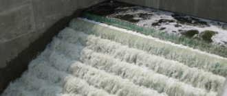
During the process of precipitation and snow melting, significant volumes of water accumulate on the surface of the earth, the movement of which forms fast-flowing streams. These streams wash away many different contaminants from the ground and asphalt roads. Most often these contaminants are: oil spills, sand, eroded clay and small debris.
However, streams of rain and melt water collected from the territory of industrial enterprises or warehouse complexes, in addition to suspended solids and petroleum products, can contain very dangerous and even toxic substances.
Catalog of storm water treatment stations
Name of BAZMAN series rainwater treatment systems
BAZMAN LOS-PP-C-OKF
- BAZMAN is a trademark;
- VOC - storm water treatment plant;
- PP - polypropylene (body material);
- C - cylindrical (body shape);
- OKF - settling tank, coalescent block, sorption filter
| Name | Productivity, l/s | Volume, l | Diameter, mm | Length, mm | Diameter of pipes, mm | Neck diameter, mm | Number of necks, pcs. |
| BAZMAN LOS-PP-C 1-OKF | 1 | 1600 | 955 | 2300 | 110 | 700 | 2 |
| BAZMAN LOS-PP-C 3-OKF | 3 | 1900 | 955 | 2700 | 110 | 700 | 2 |
| BAZMAN LOS-PP-C 5-OKF | 5 | 3300 | 1250 | 2700 | 160 | 700 | 2 |
| BAZMAN LOS-PP-C 7-OKF | 7 | 4200 | 1250 | 3500 | 160 | 700 | 2 |
| BAZMAN LOS-PP-C 10-OKF | 10 | 6800 | 1250 | 5600 | 160 | 700 | 2 |
| BAZMAN LOS-PP-C 15-OKF | 15 | 9800 | 1570 | 5100 | 160 | 700 | 2 |
| BAZMAN LOS-PP-C 20-OKF | 20 | 16200 | 1570 | 8400 | 200 | 700 | 3 |
| BAZMAN LOS-PP-C 25-OKF | 25 | 20400 | 1900 | 7200 | 250 | 955 | 3 |
| BAZMAN LOS-PP-C 30-OKF | 30 | 24600 | 1900 | 8700 | 250 | 955 | 3 |
| BAZMAN LOS-PP-C 35-OKF | 35 | 26000 | 1900 | 9200 | 250 | 955 | 3 |
| BAZMAN LOS-PP-C 40-OKF | 40 | 27000 | 1900 | 9600 | 315 | 955 | 3 |
| BAZMAN LOS-PP-C 45-OKF | 45 | 30000 | 1900 | 10600 | 315 | 955 | 3 |
| BAZMAN LOS-PP-C 50-OKF | 50 | 31100 | 1900 | 11000 | 315 | 955 | 3 |
| BAZMAN LOS-PP-C 60-OKF | 60 | 33700 | 1900 | 11900 | 315 | 955 | 3 |
| BAZMAN LOS-PP-C 70-OKF | 70 | 36800 | 1900 | 13000 | 315 | 955 | 3 |
| BAZMAN LOS-PP-C 80-OKF | 80 | 37900 | 1900 | 13400 | 315 | 955 | 3 |
| BAZMAN LOS-PP-C 90-OKF | 90 | 44000 | 2200 | 11600 | 315 | 955 | 3 |
| BAZMAN LOS-PP-C 100-OKF | 100 | 48600 | 2200 | 12800 | 315 | 955 | 3 |
| BAZMAN LOS-PP-C 120-OKF | 120 | 58500 | 2200 | 15400 | 315 | 955 | 3 |
| BAZMAN LOS-PP-C 140-OKF | 140 | 67700 | 2300 | 16300 | 500 | 955 | 3 |
| BAZMAN LOS-PP-C 150-OKF | 150 | 70500 | 2500 | 14000 | 500 | 955 | 3 |
| BAZMAN LOS-PP-C 200-OKF | 200 | 80000 | 2500 | 16600 | 500 | 955 | 4 |
| BAZMAN LOS-PP-C 250-OKF | 250 | 108000 | 3000 | 15400 | 500 | 955 | 4 |
| BAZMAN LOS-PP-C 280-OKF | 280 | 124000 | 3000 | 17600 | 600 | 955 | 4 |
Elements of storm sewer treatment facilities
Sand traps Sand traps perform the function of purifying wastewater from suspended solids and coarse impurities
Oil traps Oil traps are designed to purify surface wastewater from oil products
Sorption filters Sorption filters perform additional purification of rainwater runoff from pollutants
Request a call
Get a consultation
Wells
Distribution well Distributes the flow of wastewater by directing one part of the flow to treatment, the other to the bypass line
Rotary wells Installed in places where the direction of the sewer route changes and in straight sections
Inspection wells Designed for access to the sewer system, monitoring its operation and cleaning
Pressure dampers Perform the function of damping the force of the supplied water pressure to avoid possible water hammer
Sampling wells Monitoring wells are designed to take samples to check the status of wastewater contamination
Technical wells Designed for installation of additional equipment: ultraviolet lamps, crushers, pumps
Payment and delivery
Payment for equipment can be made in cash at the supplier's cash desk, or by transferring funds to a bank account, based on the supply agreement, specifications and invoice for payment.
Equipment can be picked up at the address: Krasnodar, st. Demus 6.
We organize delivery of products by transport companies to the buyer’s site. To transport oversized cargo, low-loader trawls are used that have permission to transport oversized cargo.
Get advice from the chief engineer
Order equipment
Leave a request, we will contact you, advise and select equipment
We'll call you back within 5 minutes
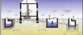
Design and principle of operation of storm sewer treatment facilities
The rainwater treatment system is a horizontal cylindrical tank, divided by internal partitions into compartments (chambers), in each chamber the water is purified from certain pollutants. A receiving and distribution well is installed in front of the treatment station.
- The first stage of cleaning is mechanical. For this purpose, sand separators are provided; they clean surface runoff from mechanical contaminants - sand, dirt, dust, leaves, and various debris. This cleaning step is carried out in the first chamber of the stormwater treatment plant;
- The second stage is wastewater treatment from petroleum products (fuels and lubricants, machine oils). Produced in an oil-gasoline separating chamber equipped with thin-layer coalescent modules;
- The third stage is post-treatment in the sorption compartment, here the final purification of surface wastewater from remaining oil products and suspended substances takes place; for this purpose, sorption filters with natural sorbent material are installed in the third chamber
- Sampling well - installed at the outlet of the station, and is used to take samples of purified water in order to determine the quality of purification
VOC Certificates
Documentation:
Certificates
Drawings for AutoCAD
Surface water treatment indicators
| Index | At the entrance | At the exit |
| Suspended substances, mg/l | 1000 | 3,0 (1,5)* |
| Petroleum products, mg/l | 500 | 0,05 |
| BOD, mg O2/l | 30 | 3 |
*When installing an additional filtration stage with sorbing media
With these indicators of storm water treatment, water disposal can be carried out into fishery reservoirs
Get a consultation
Get advice on VOC
Operating conditions and warranty
The manufacturer's warranty on cleaning systems is 2 years, from the date of delivery of the product to the buyer. Warranty obligations are canceled if the buyer makes changes to the design of the product, if operating rules are violated, as well as if the requirements are not met or deviated from the installation manual.
Operating requirements and installation instructions are specified in the documentation, which is available for download in pdf format.
- Passport for storm drain treatment facilities
- Installation instructions for polypropylene products
Stormwater treatment plant with bypass line
When installing storm sewer treatment facilities, a prerequisite is the installation of a bypass (bypass) line, this is an emergency pipe with a system of rotary wells, it is designed to drain wastewater exceeding the design indicator, bypassing the housing of the treatment system, this is called a conditionally clean drain.
We offer you equipment with a built-in bypass line; now there is no need to install a system of rotary wells and laying extra pipes; the bypass line, through which runoff exceeding the design values is discharged, is already built into the storm water treatment station.
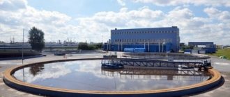
Experience in implementing VOCs
During its existence, our company has successfully implemented projects for stormwater treatment facilities throughout Russia. The equipment developed and manufactured by Engineering Ecology LLC is successfully operated at such facilities as the MIG aircraft manufacturing plant, the SAINT-GOBAIN building mixtures plant, the Ostendorf Kunstsoffe plastic pipe production plant, the Ice Sports Complex named after. Irina Slutskaya", hypermarkets "Metro Cash&Carry", furniture factory "Stylish Kitchens". We rely on our reputation, and most importantly on the reputation of our business partners, so we supply equipment that meets all modern environmental and construction standards, the quality of cleaning corresponds to the declared one.
Storm sewerage is a complex multi-component engineering system that requires professional, meticulous development and a qualified approach. Storm treatment facilities, in turn, are an integral part of the storm sewer system, without which it is impossible to commission the facility. By choosing Engineering Ecology LLC as a supplier of VOCs, you receive high-quality, durable equipment made in Russia.
Buy storm water treatment facilities
We produce local treatment facilities for surface wastewater; our equipment includes a set of ready-made solutions and is completely ready for use and installation at your site. The bodies of surface runoff treatment plants are made of reinforced polypropylene; they are durable and not susceptible to corrosion and aggressive environments.
To select a cleaning system, you can contact our specialists at the indicated numbers. We provide delivery and installation of cleaning equipment.
Request a call
Request a call
Product List
Sewage pumping stations KNS - Equipment for pumping wastewater
Polypropylene containers Polypropylene containers with a volume of up to 150 m3
Fire tanks made of polypropylene Fire tanks made of polypropylene and fiberglass
Rainwater drainage design
The design and installation of storm drainage is carried out taking into account several determining factors:
- volume of precipitation;
- soil type;
- mechanical load on the area;
- type of territory served;
- the final destination of the purified liquid.
Based on this data, the type of storm drain is selected (open or closed). The external arrangement of channels does not require large costs for materials, installation and maintenance. It is enough to stretch the gutters in the direction of the pond and distribute the sand catchers.
To lay communications underground, a larger number of constituent elements will be required, as well as a drainage embankment. This is a more complex type of sewerage, which requires knowledge of the properties of the materials used and the behavior of the soil during seasonal changes. But this approach practically eliminates the formation of puddles and allows the use of the site without restrictions.
For mountainous regions, the option of constructing a drainage-adit system is being considered. It is designed to drain groundwater. The design is represented by vertical wells and horizontal gutters with a slight slope.
Installation of storm drain treatment facilities
Stormwater treatment systems are installed underground. They may consist of one or more housings, depending on the specific installation model. Typically, VOCs are produced from the following materials - polypropylene, polyethylene, fiberglass.
Installation of storm water treatment facilities made of polypropylene is carried out in accordance with building codes for the installation of polypropylene tank equipment. The treatment system housing is installed on a reinforced concrete base, which is leveled with a compacted sand cushion.
If there is a high level of groundwater in the area where the equipment is installed, then the body of the treatment plant is attached to the reinforced concrete base using synthetic tie belts using embedded parts mounted at the concrete pouring stage.
Then the installation of a distribution well and a bypass line consisting of a bypass pipe and rotary wells is carried out; if the rainwater treatment plant is equipped with a built-in bypass line, then the installation of bypass pipes is not required.
Backfilling is carried out with coarse sand with layer-by-layer compaction. When backfilling equipment, you should avoid getting solid soil particles, frozen lumps of sand, stones and foreign objects that could damage the body of the treatment system.
Simultaneously with backfilling, the treatment station is filled with water up to the level of the outlet pipe.
Request a call
Request a call
Types of rainwater drainage
The system can be open or closed. An open storm drain involves the location of several trays on the site for transporting water to collection tanks. For natural storm drainage, drainage is done on the surface of the soil, while water is absorbed into the soil. Laying of modular open road storm drainage channels is carried out without compromising the integrity of the coating.
The closed point type of storm drain requires professional skills, since pipes and other elements are laid in the ground, connecting to the drainage. Most often, a combined option is used, which combines the advantages of both systems.
Types of surface runoff treatment facilities
One of the main conditions for the high performance of a stormwater treatment plant is the same average flow of wastewater into the treatment process. That is why local storm water treatment facilities must be equipped with systems that regulate wastewater flow and stabilizers of its composition.
Based on the principle of regulation of surface wastewater to be treated, VOCs are divided into two types:
- accumulative - flow is regulated based on volume;
- flow-through, flow is regulated based on flow
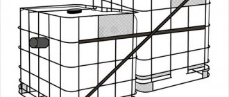
Local storage treatment facilities for surface runoff
The principle of operation of accumulative treatment systems is as follows: during rains of low and medium intensity, contaminated runoff enters the accumulator tank. A basket is installed at the entrance to the drive to filter large debris.
The storage tank is divided by partitions into several chambers; the number of chambers is determined based on the volume of the storage tank. As surface water flows from one chamber to another, the main suspended particles settle.
The floating oil film is captured by special booms containing sorbent material. The entire volume of wastewater collected in the storage tank is pumped by submersible pumps for further filtration and purification within 48 hours. After final filtration, the purified effluent is fed into the exhaust manifold.
Flow-type treatment facilities
Regulation and averaging of wastewater in local flow-type surface runoff treatment facilities is carried out by installing a separation chamber directly on the inlet collector.
In systems of this type, the following process of purification of surface calculated runoff occurs:
- gravitational settling of sand, suspended substances, soil particles, floating debris and insoluble petroleum products is carried out in a sand trap chamber;
- separation of oil products from water is carried out on corrugated blocks of a thin-layer coalescent module;
- post-treatment of emulsified petroleum products and fine particles using special sorbing filters, with filter media made from natural sorbent
During periods of intense precipitation and peak wastewater flows, surface runoff exceeding the design capacity of the treatment facility is diverted bypassing the system via a bypass (bypass) line through a distribution well installed in front of the VOC building.
Request a call
Request a call
Installation diagram of storm water treatment facilities
The standard scheme for installing a flow-type VOC is carried out with the installation of an external bypass (bypass) line, through which conditionally clean runoff exceeding the design values is discharged during periods of intense rain. The bypass line is installed bypassing the treatment plant and consists of a pipe and rotary wells.
Scheme of a flow-type treatment system
Our plant has developed a system with a built-in bypass line into the body of a local treatment plant; this technology facilitates the process of installing equipment and reduces the overall cost of construction and installation work for the arrangement of a complex of treatment facilities.
VOC circuit with built-in bypass line
Underground equipment diagram
| 1 - inlet pipeline 2 - waste container 3 - submersible pump 4 - ball valve 5 - storm inlet 6 - overflow pipeline 7 - pressure pipeline 8 - wash water pipeline 9 - waste water supply 10 - sand collection hopper 11 - purified waste water discharge 12 - low resistance drainage 13 - thin-layer block 14 - sediment pits | 15 - rotary pipe 16 - tank for oil products 17 - drainage of wash water 18 - filter with floating load 19 - float level indicator in front of the filter 20 - fire arrester 21 - floating load 22 - high resistance drainage 23 - housing 24 - cover 25 - supply pipeline 26 — sorbent 27 — drainage 28 — discharge pipeline of treated wastewater |
Calculation and selection of storm water treatment facilities
In accordance with current building rules and regulations, 70% of the total volume of storm water discharged from urban areas and enterprises of the first group are subject to treatment.
The volume of surface wastewater discharged for treatment from urban areas and production sites is determined using the maximum intensity method, using the following formula:
Woch=10*ha*Ψmid*F
Where:
- • F—catchment area Ha;
- • ha - the maximum amount of precipitation during the period of rain, from which the runoff is diverted for treatment in full (for the calculation, observation data from meteorological stations for precipitation in a specific region in the interval of 10 - 15 years are taken);
- • Ψmid - average value of the runoff coefficient for the calculated rain (data taken from table 14 SP 32.133330.2012);
The performance of flow-through surface runoff treatment systems is determined by the formula:
As you can see, performing these calculations is not a simple task, which can only be done by specialists with specialized education. It would be better to entrust it to the employees of design organizations.
Leave a request for calculation and selection of a treatment facility
Order VOC calculation
Calculate VOC