How a drainage system project is created
It is advisable to develop a drainage system design at the stage of site development, since surface and groundwater can have a destructive effect both on green spaces on the site and on buildings. This approach will allow us to effectively and comprehensively solve the problem of flooding and avoid unnecessary financial and labor costs. But our company’s employees can carry out drainage even after construction. It will just take longer and, accordingly, will cost a little more.
The design of drainage systems in our company is regulated by the relevant regulatory documents - SNiP 2.06.15-85 and 2.04.03-85 and is based on modern developments of such organizations as Mosproekt, Research Institute Mosstroy, etc. in the field of drainage from polyethylene pipes with a filter shell.
Information you need to work on your drainage project:
- Site plan with buildings marked on it and indicating the depth of foundations
- Topographic survey of the territory (for complex reliefs or complex geoplastics - mandatory, for flat areas with simple relief - optional)
- A landscaping map (denroplan) is necessary to link the drainage system to the planned landscaping areas
- A road and path plan is needed in any case (for the effective collection and drainage of water from paths and solid paving areas)
- Geological and hydrological data of the developed area. This data may not be needed if the building site on which the site is located has already been studied and the soil has the same structure. Those. There is no need to re-order “geology”.
- Communication plan for the territory (existing and planned).
Construction of drainage trenches: structure overview
As you can see, both SNiP and “folk” craftsmen recommend equipping a foundation drainage system only with the help of trenches. Therefore, below in the text we will consider the construction of a drainage pit.
Foundation trench
The foundation trench is formed by the wall of the foundation itself and the slope of the foundation pit. It is filled with two types of soil - a permeable sand-gravel mixture and ordinary sand selected during the construction of the pit.
Moreover, permeable (drainage) soil is laid closer to the foundation wall, fixing it with the ballast method. As a result, the layers in the foundation trench are separated vertically.
Well, at the bottom of such a trench there is a layer of crushed stone (with a drainage pipe inside) and a layer of permeable soil.
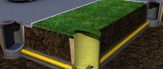
The bypass trench is dug separately. It is buried half a meter below the base and filled with horizontal layers - 50 centimeters of crushed stone (with a drainage pipe inside), a layer of geotextile (protection from silting of the pipe) and a layer of sand (to the very zero level).
The upper part of such a drainage system is not protected, which allows the use of a bypass drainage system to also remove atmospheric moisture (and high water).
Types of drainage used in drainage system projects
Extract from SNiP 2.06. 15-85 (clause 3.23 “Engineering protection of the territory from flooding and flooding”): “When choosing systems of drainage structures, the shape and size of the territory requiring drainage, the nature of groundwater movement, geological structure, filtration properties and capacitive characteristics of aquifers must be taken into account , the area of distribution of aquifers, taking into account the conditions of recharge and discharge of groundwater, the quantitative values of the components of the groundwater balance were determined, a forecast was made for the rise of the groundwater level and its reduction during the implementation of protective measures.”
Drainage systems used today are classified according to many criteria - by landscape architecture objects, by target orientation, by design, by principle of operation, by materials used, by hydrogeological conditions and soil properties. Here are just a few of them, the most relevant for drainage of plots for private households.
According to the design of the watercourse, drainage can be:
Open (cavitary)
– the simplest to implement. Along the perimeter of the site, trenches are dug with a depth of 0.6-0.7 m and a width of 0.5 with the walls deviating from the vertical to the outside by 30°. Open drainages serve to collect and redirect melt and rainwater in areas located on slopes.
Backfill (cavity with filler)
— it is arranged as follows: the bottom and walls of the trench are lined with geotextile, which acts as an additional filter material and prevents silting of the drainage. Geotextiles are laid out so that they protrude 30 centimeters on each side of the ditch. Then half the trench is filled with broken bricks and large crushed stone, after which finer material is poured almost to the top. The filling of the ditch is covered with the edges of geotextiles, soil is poured on top and turf is laid.
Closed (tubular)
- differs from backfill in that in a ditch, on a prepared bed of sand and crushed stone, drainage pipes are laid at a certain slope. Then a water-carrying layer of sand and crushed stone is created on top of the pipes. Geotextiles are used as in the previous case. The scheme of a closed-type drainage system is usually made in the form of a “herringbone” (there may be other configurations). Water from the side channels flows into the central one and is discharged to the water discharge point.
According to the principle of operation, drainages are distinguished:
- systematic
(evenly distributed throughout the site) - selective
(the drainage system is laid selectively for individual sections of the territory) - cut off
(head) - to intercept and redirect groundwater that comes from outside (for example, during flooding).
According to soil and hydrogeological conditions:
- horizontal drainage
- differs in that the drains are laid horizontally with a calculated slope towards the discharge of water - vertical drainage
- is a system of wells and boreholes.
By types of landscape architecture objects:
- double drainage
- installed in areas where a high density of trees and shrubs is planned, due to which repair of the system in the future will be difficult - coastal drainage
– carried out in river floodplains - wall drainage
- to drain water from the walls and foundation of a building - reservoir drainage
- used in cases where water accumulates under a site or structure.
Drainage installation
You can install the drainage system yourself.
The instructions must be followed. To organize linear surface drainage, you need to dig a trench to lay gutters. A cushion of concrete or DSP is laid under them. For a deep type of drainage system, more effort is required to lower the height of water flow underground:
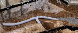
1.first, they dig a trench, cover the bottom and walls with geotextiles.
2.The bottom is lined with a gravel cushion.
3. The pipes are wrapped in geofabric and placed in a trench.
4. gravel is poured on top.
5. Geofabric is laid on top with another layer.
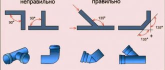
The pipeline is laid at an angle of inclination for gravity flow of liquid into the collection well. Inspection wells are made in turning areas. Common installation mistakes:
1. The drains are too far apart.
2.pipes are laid shallowly underground.
3.wells are located close to each other.
4.non-observance of the angle of inclination, or lack thereof.
5.poor debris filtration system.
6. Incorrectly selected pipe diameter for the system.
Drainage system design
The design of the system begins with geodetic and hydrological calculations of the site. This work is done to determine operating conditions, as well as the structure of the drainage system, as well as its key indicators.
The project must contain:
- Diagrams and technical drawings of the sewerage system and all its components, both on the surface and underground parts
- Installation properties of drainage systems - diameters, dimensions, installation depth and slope of the drainage pipe. SNiP gives standards for these values
- Dimensions of all components that make up the network - manholes, connectors, fittings and other parts
- Technical and economic budget for the construction of drainage systems
The project documentation must include the following specifics:
- Geomorphology of this site
- Features of the climate of the territory in which it is located
- Groundwater level markers
- Characteristics and structure of soils
- Distance of water bodies from the construction site
Open drainage in a summer cottage: the easiest way to secure the cellar and foundation
Of course, when installing drainage in summer cottages, you can get by with banal ditches. And yet, nowadays there is a great variety of material that will help make drainage more aesthetically pleasing and beautiful. And it’s quite easy to completely hide highways from view if the need arises. And since the drainage scheme as a whole depends on the purpose of the drained area, it makes sense to understand the nuances, understand how the drainage system on the site should be arranged, and what features there are for drainage from buildings or cellars.
It is important to know! The blind area around buildings and structures, drainpipes and other similar devices are also part of the drainage, and therefore their role should not be underestimated. On the contrary, improperly organized drains from the roof of a building can significantly worsen the removal of water from the local area, nullifying all the efforts of the home craftsman
So, let's start with the most important, from the point of view of necessity, drainage - around residential buildings
How to make drainage around the house - practical tips and tricks
The main task before making drainage around the house is to choose the right place for the well into which rainwater will drain. At the same time, it must be designed in such a way that it does not have to be pumped out periodically. Also, do not forget about sand traps in gutters.
In general terms, the work is done as follows. A shallow trench is dug along the perimeter of the building and connected to a well. Moreover, it must have a slope that can be measured using a building level. Next, the bottom of the dug trench is filled with sand and compacted. Gutters are laid inside, which can be either open or closed with a special mesh. It prevents large debris and leaves from entering the drain.
Important advice! How the drainage will function depends on the slope of the gutter and its correctness. Therefore, it is necessary to measure it very carefully.
The nuances of drainage in a summer cottage
Such water diversion is done to protect plantings from flooding. Mainly used in areas with marshy soil and where the groundwater level is quite high. The essence of such a drainage device is as follows. It is necessary to dig trenches along the site, about half a meter deep, into which you will then need to lay perforated pipes. A sand cushion is made for them on a special fabric. Thus, excess water, again, will fall into the well.
Another way to prevent groundwater from entering the site could be to install gutters around the perimeter. But the most convenient method will be the method of reservoir drainage. In this case, gravel of various sizes is poured into the dug trenches, after which they are covered with turf. Today, this is the cheapest of all drainage methods, and therefore the most common. It is worth noting that with all the availability of site drainage systems, few people begin such work. And this is a big mistake. After all, the installed water drainage does not cause any inconvenience, and it has quite a lot of positive qualities.
Draining soil around garages and other buildings
How to make drainage in a garage and what it is needed for are the most common questions that a home craftsman faces when designing such systems. You need to understand that draining groundwater from a room will not only preserve its foundation. After all, many people have a cellar located in the garage, which means it is necessary to protect it from flooding. Of course, there is another way out, such as installing a sealed box (caisson), but over time it will rot. And this design is quite complicated to install.
But even if there is no cellar or inspection hole, drainage in the garage will not hurt. After all, in winter, melted snow will drip from the car, which, evaporating, will greatly humidify the air. And if there is a drainage system, the humidity will remain normal.
Is installing drainage in the basements of houses an extravagance or a necessity?
Some argue that if there is drainage on the site and around the house, then there is absolutely no need for it in the basement of the building. This is a fairly common mistake. Water can also penetrate below the street drainage. And there is no need to say what consequences this can lead to - probably everyone understands this well.
It is most convenient to carry out drainage at the construction stage, i.e. laying the foundation. But even if this was not provided for, there is still a way out. It is possible to drain water even in rooms with concrete floors. We will look in more detail at how to perform such work a little later.
Existing technologies for installing a drainage system
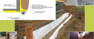
Scheme of closed drainage on the site.
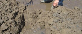
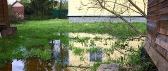
The need for drainage is quite easy to determine. It is needed when the soil on the site consists of clay and various types of loam. After rains, large puddles form in the area. In this case, the terrain of the site can be either flat (water has nowhere to flow) or inclined and located at the bottom (water flows into it from the top point of the site). In both cases, you simply cannot do without a drainage system.
To carry out the work of creating a drainage system we will need:
- pipes;
- couplings;
- fitting;
- wheelbarrow;
- 2 shovels: shovel and bayonet;
- hacksaw;
- roulette;
- level;
- rail;
- tamping;
- sand;
- crushed stone;
- gravel (fraction 2-4 cm);
- geotextiles.
Drainage systems are divided into 3 main types: open, closed and backfill. The simplest is an open system. Its structure is as follows. A ditch 70 cm deep and approximately 50 cm wide is dug along the perimeter of the site. The slope of the ditch wall should be 30 º. All the water flows out of it through drainage systems into a large drainage ditch that serves several areas at once. This method of drainage is very effective during snow melt in the spring and heavy rains in the fall.
Higher up the slope, a transverse interception ditch should be dug. It collects water flowing from the upper part of the site. From its two ends, drainage channels extend downwards at an angle, connected to a large common drainage ditch.
Sectional diagram of the drainage system.
The open drainage method is an acceptable option only for areas with a small area and a uniform topography. If the area is large and, in addition, characterized by different heights (sometimes with slopes in different directions), then it will be necessary to equip a closed or backfill drainage system.
Both systems are quite similar in technology. The only difference: a closed drainage system involves laying special perforated pipes in the ditches. With backfill technology, broken bricks or large crushed stone are poured into ditches, on top of which a layer of finer gravel or soil is laid. Water is filtered through the filler. It goes in a given direction along the clay outlet.
You can protect buildings and plantings from excess moisture by following the rules for drainage.
If the drainage system is considered closed, then it involves creating a trench in the ground, the depth of which is 70-150 cm and the width is 25-40 cm. It is extremely important to provide in advance a slope directed towards a natural or artificial water intake.
The slope based on which the drainage system is installed is described by SNiP as follows:
- - slope value 2 cm per 1 linear m, - on clay soil
- - 3 cm per 1 linear m, - on sandy soil.
Option for a drainage system with a slope angle of 2 cm per 1 m (i=0.02):
The bottom of the resulting depression is covered with a dense layer of crushed stone. Drains are laid on it, then everything is covered again with crushed stone. After this, the system is backfilled with soil.
Wastewater flows through drainage pipes, collects in a collector and ultimately flows into a water intake (river, pond, etc.).
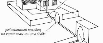
Control of work on the drainage system occurs through special inspection wells, which are built from polymer or reinforced concrete rings.
IMPORTANT:
When the drainage system is initially installed correctly, the groundwater level does not rise above the permissible point, but, on the contrary, begins to decline. Thanks to this, the soil fertility in the area increases noticeably. If the drainage system is not built or errors were made in its installation, the negative impact on the soil as a whole cannot be avoided.
Project Creation Basics
Design is the initial stage in any work. This directly applies to the creation of a drainage system.
Wall drainage diagram.
When designing a drainage system, the following factors are taken into account:
- level of resistance of soil rocks to the process of washing out particles;
- permeability indicator of individual rocks;
- the presence of tectonic disturbances on the site;
- composition of groundwater;
- location of sources recharging groundwater and their intensity.
The drainage plan must comply with the provisions of current regulations. The main requirements are:
- the size of the slope from the top point of the pipeline to the drainage structures is 0.5-0.7%;
- the presence of elements that control the functioning of the system and flush it;
- the bottom of the pipe is located 20 cm below the foundation level (if the drainage is close to the house)
If possible, the plan should include the installation of inspection wells. They should be installed in places where the pipe turns.
What is SNiP?
SNiP is an abbreviation derived from “Building Norms and Rules”. According to these codes, the requirements of various organizations for the implementation of sewerage, drainage, various buildings and other engineering structures are determined. SNiP takes into account ergonomic, economic, architectural, and technical characteristics that must be met.
Drainage project according to SNiP
Why comply with SNiP if sewerage, drainage or any other communication works like this:
- Any construction must be legalized, be it the construction of an extension near the house or the installation of a sewer pipeline. If you did not comply with the standards stated in the regulatory document, then the project will not be legal. Government organizations can force you to rebuild the pipeline or even fine you;
- SNiP not only helps to build drainage systems correctly, but also contributes to certain savings. The document identifies many ready-made solutions for drainage design that are least expensive for the owner;
- Communication carried out according to certain standards is more effective and durable. It is less susceptible to the negative effects of groundwater, seal failure or other factors.
SP drainage systems
Design of external sewerage, gutters and drainages
6.1.1 The selection of pipes should be made taking into account the composition of the wastewater, its temperature, based on hydraulic and strength calculations.
6.1.2 For gravity sewerage, sewer pipes should be used. The use of pressure pipes must be justified.
6.2.1 For non-pressure sewerage, smooth pipes are standardized in outer diameters, except for pipes made of glass and basalt plastics manufactured by winding.
Pipes are divided into classes according to the ring rigidity of the shell: flexible, semi-rigid and rigid. The class of pipes is given in Appendix A.
6.3.1 Gravity sewerage pipelines should be provided with both detachable and permanent connections.
6.3.2 As detachable connections, socket connections should be used, sealed with rings of various profiles.
6.3.3 The main types and methods of pipe connections are given in section 3.3.
6.3.4 For sewage pressure pipelines, predominantly permanent connections should be used - gluing and welding.
6.3.5 Detachable connections (flange, etc.) on pressure sewers are usually used to connect pipes to equipment.
6.4.1 The routing of external sewerage must be carried out taking into account the requirements of SNiP 2.04.03.
6.4.2 Gravity sewerage pipelines should only be straight. Changing the diameter of the pipeline and its direction is allowed only in wells.
Pressure sewer systems are performed in accordance with section 5.
Calculation of gravity pipelines for strength should be carried out according to the method given in Appendix D.
Hydraulic calculations of gravity underground sewerage pipelines are carried out according to the formulas given in section 4.5.
6.7.1 The need to compensate for thermal elongation of pipes in pressure sewers is established by calculation in accordance with Section 3.7 of this Code of Practice, taking into account the pinching effect of the soil.
When the pipeline is pinched by soil, the elongation of the pipeline decreases. The amount of decrease in D lum is determined by the formula
where f
t is the coefficient of friction of the material on the soil, determined experimentally; in the absence of data, it can be approximately taken equal to 0.4,
g - volumetric weight of soil, N/m 3,
H
— depth of pipeline, m,
L
— pipeline length, m,
E
szh is the elastic modulus of the material in the direction of deformation, Pa,
s
— pipeline wall thickness, m,
Ky is the soil compaction coefficient, taken equal to 1 for a degree of compaction of 0.95 and 0.5 for an uncontrolled degree of compaction when backfilling a trench.
6.7.2 Compensation for temperature deformations of pipelines in gravity sewers is provided by:
- socket joints sealed with rings,
- partially in sewer wells by constructing a passage through the walls of the well and filling the tray.
6.8.1 For drainage systems, it is allowed to use sewer, drainage and water intake wells made of: polymeric materials (PE, PVC, etc.), combined (elements made of polymeric materials in combination with elements made of reinforced concrete), reinforced concrete and brick. The dimensions of the wells must correspond to those specified in SNiP 2.04.03.
6.8.2 Wells made of polymer materials should be used in conjunction with a protective slab made of reinforced concrete and traditional metal hatch elements.
6.8.3 The tray part of manholes made of polymeric materials must have ready-made trays made of polymeric materials, as well as protruding pipes for connecting the pipeline.
Guide on how to make foundation drainage
When constructing buildings, a drainage system must be installed. High-quality drainage allows you to avoid many problems during the operation of the building (for example, the appearance of dampness in the basement of the house, cracking of the foundation), protects the building from precipitation, ensures uniform distribution of groundwater throughout the site, protects the flooding of the basement and ground floor of the building, and therefore prevents mold and foundation destruction. Read the instructions on how to make a foundation for a gazebo.
No building will last long enough without foundation waterproofing equipment and without a well-equipped drainage system.
Is wall drainage around the house really necessary? Construction nuances
Wall drainage is arranged to drain rain, melt and ground water (rising during flood periods) from the foundation. When is its installation necessary, and when can you do without building a drainage system around the house? Features of wall drainage, project preparation.
Wall drainage device
Schematically, the drainage system near the foundation can be designated as follows:
- a closed network of perforated pipes around the house, made with a single slope towards the lowest point,
- where the prefabricated well is installed,
- from there the water leaves the site,
- inspection and cleaning of the system is carried out through inspection wells installed at every second bend.
Of course, during the construction of a building, the foundation is protected with waterproofing materials. But even with the highest quality, the destructive effects of excess liquid will appear after five years. And it is better to prevent this negative moment. Using foundation wall drainage.
When is its construction obligatory?
To answer this question, a hydrogeological map of the site is needed. Surveys are carried out at a depth of three to four meters. The composition of the soil is studied, topographic surveys are carried out, and the location of buildings on the site is planned.
SNiP for wall foundation drainage names the following conditions:
- basement floors, technical undergrounds, intra-block collectors, communication channels are located below the groundwater level or the distance from the floor to groundwater is less than fifty centimeters,
- basement floors, technical undergrounds, intra-quarter collectors, communication channels are located in clay and loamy soils (the groundwater level is not important in this situation).
In the first case, wall drainage will protect the basements and foundation from the seasonal rise of groundwater. In the second - from seasonal swelling of the soil (clays and loams do not conduct moisture well, water accumulated in the soil in autumn freezes in winter).
Ways to protect the foundation from moisture
The drainage system around the building is arranged in two ways:
1. Surface drainage.
Today, more and more people prefer a deep system that is hidden from human eyes and does not violate the design. The area above the drainage can be used for planting plants and creating flower beds.
Wall drainage section:
A closed drainage network is a continuous pipeline covered with a sand and gravel mixture. The pipes have perforations and stiffening ribs, due to which the strength margin in the cross section increases.
When designing wall drainage, a number of conditions must be observed:
1. Drainage pipes are laid with a slope of one and a half to two centimeters per linear meter. The direction of the slope along the entire perimeter is the same - towards the lowest point, collection well or collector.
2. The optimal distance between inspection wells on a straight section of the pipeline is forty meters.
3. Drainage structural elements must be below the soil freezing level.
4. Drains are laid at a distance of three or more meters from the foundation.
When drawing up a wall drainage diagram, calculate the slope and diameter of the drains. The throughput of the entire system depends on this.
Drying installation technology for another type of foundation - strip and columnar
We do the following work:
- we make a ditch around the foundation of the structure;
- we clear the base of the structure from the soil;
- we take a technical break to allow the base to dry;
- apply a bitumen primer to the foundation;
- we take a technical break - 2-3 days;
- apply bitumen mastic to the dried base;
- glue the reinforcing mesh onto the mastic;
- we take a technical break - a day;
- apply a layer of bitumen mastic to the mesh (waterproofing the foundation);
- we are constructing a collector well to which pipes will be connected;
- we dig a trench;
- fill the trench with sand - 5 cm;
- We lay geotextiles at the bottom of the trench;
- fill in gravel - 10 cm;
- lay pipes on gravel with a slope of 2°;
- we join the pipes with adapters and corner connectors;
- We make sure that at the corners of the structure all pipelines enter the inspection wells;
- We lay pipes from inspection wells that drain water into a drainage pit or collection well;
- fill the pipes with gravel - 10–20 cm;
- We cover the contents of the trench with geotextile on top;
- we fix the geotextiles with synthetic ropes, but it is possible without them;
- we fill the trench with earth or make a soft blind area (concrete can also be used).
That's all the manipulation. The drainage system is ready! Tell me, is this a very difficult job? Of course not, but I’ll be honest, it’s quite labor-intensive. But it is of enormous importance!
If the drainage structure is constructed correctly, no moisture is harmful to the foundation of any building. Thus, the drainage system is a guarantee of the durability of your cozy home!
CALCULATIONS FORECASTING FLOODING OF TERRITORIES
2.10.
Forecasts of flooding of territories include calculations of the formation of perched water on impermeable lenses within the aeration zone, the formation of new technogenic aquifers and the increase in groundwater levels in existing ones. These issues are discussed below in the given order. Let us note that in this work, only in a very schematic form, the issues of forecasting the flooding of territories due to the backwater of groundwater during the construction of hydraulic structures and irrigation of farmland are addressed.
Formation of perch on waterproof lenses in the aeration zone
2.11.
Within the aeration zone, as a rule, there are very often lenses of water-resistant rocks on which infiltrating water accumulates (Fig. ), with the formation of perched water. With the periodic supply of infiltration nutrition, the perched water formed on such lenses is temporary, and with constant infiltration, a technogenic lens of groundwater is formed (technogenic perched water). The planned dimensions of the technogenic perched water are determined by the contours of the lens of waterproof rocks; the maximum height of the water layer depends on the permeability of the rocks and the intensity of infiltration.
2.12.
In the case of elongated waterproof lenses (when their length is more than 5 times the width), water filtration in plan can be considered flat.
The process of formation of perched water (Fig., a
) is described by the formula
(2)
Where
= x
/
L
;
f
0 =
at
/
L
2;
hc =
;
mn
are the roots of the equation
mn
tan
mn
=
Bi.
The series in formula () converges very quickly and in calculations you can limit yourself to two or three terms.
The limiting (stationary) position of the water level of technogenic perched water is determined by the dependence
(3)
Rice. 1. Schemes for the formation of technogenic perched water in the aeration zone on impenetrable lenses of elongated ( a
)
and
round (
b
) in terms of shape.
To facilitate calculations using the formula () in app. and the values of An
and
mn
borrowed from [].
2.13.
In calculations, rectangular or rounded waterproof lenses must be replaced with round ones with a given radius
R
(Fig.,
b
), the method for determining which is indicated above. To calculate the process of formation of perched water on round waterproof lenses, the formula is used
(4)
Here J
0 (
x
),
J
1 (
x
) — Bessel functions of the first kind;
n n
are the roots of the equation
n n J
1 (n
n
) =
Bi J
0 (n
n
).
The first six roots of this equation are given in the appendix. . The series in formula () converges very quickly and in calculations you can limit yourself to two or three terms.
The limiting (stationary) position of technogenic perched water is calculated by the formula
(5)
Formulas () and () show that the process of formation of perched water stabilizes very quickly. It can be assumed that the duration of the non-stationary phase of perched water formation does not exceed the value t
*£ 4
nL
2/
m
21
khc
for an elongated lens and
t
*£ 4
nR
2/n21
khc
for a lens that is circular in plan.
In these relations, m
1 and n1 are the first roots of the corresponding characteristic equations. This gives grounds for not conducting a study of the non-stationary phase.
Formation of a technogenic aquifer in initially dry soils
2.14.
Technogenic aquifers are formed on the first regional aquifer from the earth's surface (Fig.) under the influence of additional infiltration recharge. In this case, a gradual accumulation of water occurs on the aquitard with the formation of a dome of groundwater that increases over time in the zone of additional infiltration. The spreading of this dome occurs along the aquifer and slows down the process of rising levels. The process of formation of a technogenic aquifer depends on the intensity, shape and planned dimensions of the source of additional infiltration; in layers of unlimited size it is always non-stationary.
2.15.
When additional infiltration occurs within a strip with a width of 2
L
(see
Fig
.,
a
), the process of formation of a technogenic aquifer is described by the formulas:
in zone I ( | x
| £
L
)
(6)
in zone II ( | x
| >
L
)
(7)
In these formulas l
(
t
) is the moving boundary of the dome spreading, it is found by the formula
The greatest rise in water level occurs on the axis of the infiltration strip; it is equal to:
2.16.
When additional infiltration occurs within a circular area with radius
r
0 (see Fig. ,
b
), the position of groundwater levels is calculated according to the dependencies:
at r
£
r
0
(8)
Rice. 2. Schemes for the formation of a technogenic aquifer on a regional aquifer in initially dry soils upon infiltration from a strip-shaped source ( a
) and round (
b
) in terms of shape
at r
>
r
0
(9)
Determination of the moving boundary of the dome spreading R
(
t
) is made by selection from the equation