In the construction of electrical and telecommunication networks, KCS, or cable communication wells, are used. These industrial structures are used as inspection or observation tanks, where, as a rule, the main coupling connections of electrical cables or other electrical networks are located. The well structure is equipped in such a way that a specialist has access to it to perform production tasks. The availability of accessible internal space allows for both installation and repair work.
Reinforced concrete wells KKS - production and application
For the production and technological application of reinforced concrete cable communication wells (CCCs), the unified technical regulations TU No. 45 are used. 1418-83. This regulation determines the standards for the production of KKS, conditions of storage, transportation, installation, etc.
For each type of product, a mandatory labeling condition is provided. The marking indicates the type of product, its structure, size and reinforcement option. In addition, the marking must also indicate the name of the manufacturer, the weight of 1 product, and the date of production.
According to typical drawings, a reinforced concrete well has two sections, called the upper and lower sections. Each section has horizontal overlaps. The top section has a hole for mounting a hatch, as well as built-in halves of the side sections. In most cases. There is a requirement for the production of a hatch - the hole must always be exclusively 600 mm in diameter.
On the walls of the structure there are so-called mounting earrings, used for pulling cables and fixing blocks, as well as ruffs used for fastening under equipment.
Maintenance of line-cable structures
Regardless of the type of structure, the necessary list of preventive maintenance is as follows:
- monitoring the condition and correct operation of fuses and arresters;
- external inspection of couplings and their correction;
- inspection of lighting and ventilation;
- checking anti-corrosion protection;
- checking for tension or slack in cables and correcting misalignments.
The service life of concrete communication collectors is about 50 years; some manufacturers claim that the service life is 70 years.
Plastic collectors for utility networks must be protected from temperatures exceeding the threshold of 70 °C, but the number of freezing and defrosting cycles does not affect the operation of the product. Their estimated service life is about 50 years.
Classes and groups of reinforced concrete connection wells
Depending on the form of execution, all KKS are grouped into classes - round, prismatic, square. According to the technical specifications, the following form of installation of the KKS is allowed:
- stationary CCS;
- corner KKS;
- pass-through KKS.
In addition, there is a special marking for wells, like this:
- a typical well is marked KKS;
- special, marked KKSS;
- stationary with marking KKSst.
This type of marking must be present on the reinforced concrete product. In addition, according to the technical specifications, each type has its own gradation of standard sizes.
- KKS wells – 5 standard sizes.
- KKSS wells – 2 standard sizes.
- KKSst wells – 4 standard sizes.
For the latter case, it is necessary to understand that the well is designed for the capacity of the automatic telephone exchange station, that is, from 3 to 20 thousand numbers. If the station capacity is over 20 thousand numbers, a special design of the finished product is used.
Additional equipment
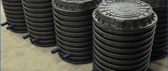
To align inspection collectors with the level of the road surface, support concrete rings of the KO-Ch and KO-ChP types are used. They are installed on top of the tank, and a cast-iron hatch is mounted inside the structure. For fastening, cement mortar and special components such as SNKL are used. For CC under sidewalks, lighter hatches with reinforced concrete rings KO-1 with a height of 10 cm and KO-2 with a height of 15 cm are required.
Brackets with ruffs are mounted after assembling the entire structure in special holes. Ruffs are necessary for attaching the brackets.
| Well brand KKSr GEK | Bracket size | Number of brackets in KKS | Number of ruffs |
| 1 | KKP-60 | 4 | 8 |
| 2 | KKP-60 | 4 | 8 |
| 3m | UKKP-60 | 8 | 16 |
| 3 | KKP-130 | 4 | 8 |
| 4 | KKP-130 | 4 | 8 |
| 5 | KKP-130 | 6 | 12 |
| KKSS (block SB-1 GEK) | KKU-160 | 2 | 4 (on block SB-1) |
In addition to standard consoles made of cast iron, it is possible to equip it with special consoles made of steel. They are necessary for mounting optical couplings MOG and MTOC. In already filled shafts, steel optical consoles are installed - KSO-2 (double) and KSO-3 (triple). Installation is carried out directly on the walls of the tank without brackets at a distance of 5.5 cm from each other.
About passport load
For all types of wells, the rated load of one of the numbers 10 or 80 is indicated:
- A value of 10 indicates the possibility of installing a well on a pedestrian area or on a non-roadway. The maximum possible load is no more than 10 tons per plane.
- A value of 80 indicates the placement of the KKS on the roadway, as well as in places where there is a load on the ground. The maximum possible load is no more than 80 tons.
The specifications allow the marking to indicate an additional letter value for wells:
- the letter “y” is an angular type;
- letter “p” - branching;
- the absence of a letter is a passing type.
If the structure has a monolithic appearance, the letter “m” is indicated after the numbers. The design contains consoles and ruffs, and the additional designation GEK is introduced. If brushes and consoles are not included in the package, the letter “G” is indicated.
For example, there is a marking KKS 3-10 GEK, here the meanings are:
- KKS - cable communication well;
- 3 – standard size through passage (no small letters in the meaning);
- number 10 – maximum load is 10 tons, and the well is intended for installation in a pedestrian area;
- GEK - the package includes brushes and consoles.
Attention, wells marked KKS 1 or KKS 2 are manufactured exclusively of the walk-through type. For the rest, an additional design option is allowed - corner or branching.
The EnergoMonolit company developed its own specifications for KKS. You can request and review it by mail or telephone.
Installation
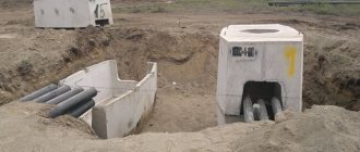
It should be noted that the rules for installing plastic wells and the process itself are no different from the actions when placing polymer septic tanks or caisson chambers in the ground; operations are carried out in the following sequence:
- Dig a pit in the ground with a margin of 100 - 150 mm from the surface of the product.
- The bottom layer of earth is compacted, to avoid further subsidence of the well, a concrete screed 50-100 mm thick is poured horizontally, or a small concrete slab is laid on the bottom.
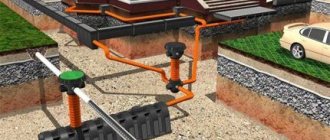
Installing a well on the road - diagram
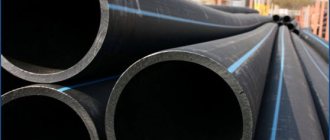
- Holes of the required diameter are cut in the side walls of the well, sealing rubber rings are inserted into them, and the product is lowered into the hole. A polymer pipeline is inserted into the cut holes, through which the telecommunications (telephone) cable will pass.
- Cement and sand are mixed in a ratio of 1:5, the resulting dry mixture is poured into the gap between the well walls and the dug hole, not reaching 100 - 150 mm from the soil surface.
- Cover the installation site with soil and lay down the removed turf.
- If the well structure is located in the area of transport movement, a concrete, cement-sand blind area about 200 mm thick is made around the hatch, or a concrete slab with a round slot of the appropriate size is placed on the neck.
The main stages of work on installing a polymer CCS
The use of plastic concrete wells is relevant for individual entrepreneurs and private construction companies engaged in the construction of construction projects on a small scale. The use of these devices can significantly simplify and reduce the cost of work on low-current, electrical, fiber-optic and telephone communications, and reduce the time required to put objects into operation.
Regulatory documentation
Since in recent years there have been changes in the production technology of cable communication wells, regulations have been approved that regulate both the production of CCS and the procedure for installation and operation.
- The main regulations are TU 45.1418-89.
- It is allowed to use the following TU and GOST for previously installed structures - TU-5855-001-92718053-2012.
- The regulatory document allowing the use of the name and other terms for the production of KKS is GOST R 50889-96. In accordance with these regulations, the full name of the KKS is “cable sewer well.”
- For the production of KKS hatches, the regulation used is GOST 8591 76.
- To install wells in sewer, gas and water supply networks, the regulation used is GOST 8020 90.
No other technical documentation is provided for the production and operation of sewer wells.
Typical designs of prefabricated reinforced concrete wells
In accordance with nomenclature requirements, the standard classification of KKS has been approved
| Classification by standard size (number or full name) | Maximum load weight, tons | Pass-through type | Corner type | Branch type | Number of input channels |
| 5 | 80 | KKS-5-80 | KKSu 5-80 | KKSr 5-80r | 24 inputs |
| 5 | 10 | KKS 5-10 | KKSu 5-10 | KKSr 5-10r | 24 inputs |
| 4 | 80 | KKS 4-80 | KKSu 4-80 | KKSr 4-80r | 12 inputs |
| 4 | 10 | KKS 4-10 | KKSu 4-10 | KKSr 4-10r | 12 inputs |
| 3 | 80 | KKS 3-80 | KKSu 3-80 | KKSr 3-80r | 6 inputs |
| 3 | 10 | KKS 3-10 | KKSu 3-10 | KKSr 3-10r | 6 inputs |
| 2 | 80 | KKS 2-80 | Not provided | Not provided | 2 inputs |
| 2 | 10 | KKS 2-10 | Not provided | Not provided | 2 inputs |
| 1 | 10 | KKS 1-10 | Not provided | Not provided | 1 input |
| I special | 80 | KKSS – 1-80 | KKSSu-1-80 | KKSSR-1-80 | 36 inputs |
| I special for existing sewer system | 80 | KKSS-1-1-80 | KKSSu-1-1-80 | KKSSr-1-1-80 | 36 inputs |
| II special | 80 | KKSS – 2-80 | KKSSu-2-80 | KKSSR-2-80 | 48 inputs |
| II special for existing sewer system | 80 | KKSS-2-1-80 | KKSSu-2-1-80 | KKSSr-2-1-80 | 48 inputs |
| V for container type NRP | 80 | KKS – 5M-80 | Not provided | Not provided | 24 inputs |
- Please note that in the standard table, the KKS 1-10 series well is not considered.
- Please note that previously sizes from 1 to 5 had a different name according to GOST - small box, large box, small type, medium type, large type.
- Please note that all stationary wells are developed taking into account the technical data for the arrangement of the automatic telephone exchange.
Areas of application of wells
Depending on the typical direction, as well as on the number of incoming block pipeline systems, existing cable systems are divided into the following types and areas of application:
- Cable stationary wells. As a rule, these structures are used for installation of various cable lines and communication systems. The installation of these wells is carried out in the immediate vicinity of workstations, points or nodes, intended for connection by a short segment. In most cases, stationary wells have a monolithic structure.
- The pass-through type is used for installation work on linear nodes for laying communication systems. It is also allowed to use communication systems in areas with slight deviations or branches, but not more than 15 degrees.
- The branching type is intended for installation in areas that have the purpose of branching, for example, on underground routes for laying utility lines simultaneously in several directions. Prefabricated devices are assembled from pass-through type or corner version of reinforced concrete KKS. The design has a complex appearance and is a large-sized structure.
- Corner designs are very different from previous options. Installation of such systems is carried out in those places where an angular rotation of 90 degrees is provided. In this case, taking into account the design documentation, the use of non-standard installation of utility lines is allowed.
For all types of wells, reinforcement instructions are a prerequisite. A special grade of steel wire is used as reinforcement, which can withstand the load specified for the KKS series.
About types of wells
As mentioned above, wells are marked KKS from 1 to 5, and each parameter has its own values.
- Type KKS-1, the well has the form of a rectangular slab, size 1030*1050mm. The working height of the well is 78 cm. The upper and lower parts are connected by welding. The upper compartment has a hole for a hatch.
- Type KKS-2, sometimes marked BTK. In assembled version. The well has the shape of an octahedron, having two parts that are hermetically connected to each other. The lower part of KKS-2 is the working bottom of a reinforced concrete structure. There is a hole in the upper part, which is used for mounting the hatch of the LC-GTS series. The total height of the structure of this model range is 1410 mm, the width is 1070 mm, and the working length is 1470 mm.
- Type KKS-3. Sometimes you can find MTK markings. The design has identical similarities with the KKS-2 series. The height of the structure is 1810 mm, length – 2010 mm, width – 1170 mm.
- Type KKS-4. The STK marking is sometimes found in documents. In terms of visual characteristics, the well has similar properties to KKS-2 and KKS-3, but differs in its impressive size. Well height – 2010 mm, width – 1300 mm, height – 1560 mm.
- Type KKS-5. Sometimes the marking TKB is found. The largest type of well, which has dimensions of height - 2010 mm, length - 3030 mm, width - 1560 mm.
Product design
Structurally, the cable well is a box-shaped structure made of reinforced concrete, located in a place that prevents flooding by groundwater. This is an underground room, accessed from above through a hatch equipped with a cast iron lid.
As a rule, its design is composite and contains 2 structural components - upper and lower. The lower element includes the bottom plate and half of the walls. Often there are designs that include a pit and a drainage hole in the bottom. The upper element contains a top plate having a hatch opening and the second half of the side walls.
Both elements have metal loops coming out of the concrete mass, used for welding when installing the product in the ground. There are through holes on the side walls for entering cable ducts. Many manufacturers, in addition to through holes, make blind niches in the walls with a wall thickness of 30-50 mm , which can be used if it is necessary to increase the number of cable entries.
During the installation of a well, the lower part of the product is buried in the ground, and the upper part is mounted on top. By welding the protruding hinges, a single structure is formed. After welding, the seam between the elements is sealed with cement mortar.
In addition to prefabricated cable wells, the industry also produces monolithic reinforced concrete products, in which case there is no need for welding work. Cable entries are installed and sealed with crushed brick on cement mortar on both sides of the wall before it is backfilled with soil, and unused niches are covered with mortar.
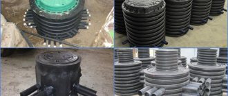
A complete cable communication well, in addition to the housing, contains 1 or several support rings, a manhole cover, a set of fastening cable brackets and brushes with which the brackets are mounted. The product is equipped with earrings designed to secure the unit when pulling cables.
In accordance with their purpose, wells are produced in several standard sizes in different designs and can have a square, quadrangular or elongated octagonal shape in the horizontal section. Some manufacturers produce products of other configurations .
Reinforced concrete cable structures are made from high-strength concrete of heavy and medium-heavy grades using special additives that increase frost resistance and resistance to deicing agents. Despite the improved characteristics of the material, viewing devices are recommended to be installed in soils that are non-aggressive to concrete.
Regulatory documentation allows for the manufacture and operation of cable wells made of brick, while a typical KKS 1 cable well has a square shape, while wells of other sizes must be built oval-shaped using special equipment.
During production, it is recommended to use ready-made reinforced concrete floors, for the bottom - reinforced concrete slabs or to concrete it in a pit. Ruffs and earrings are mounted during the formation of the walls. Upon completion of the masonry, the outer side is protected with a layer of sand-cement plaster.