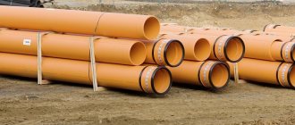
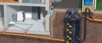
When creating communication lines and power networks that use electrical, optical and telephone cables, they are placed underground in a rigid protective pipeline made of various polymer materials. In long lines, bends, bends and branches, the protective pipeline is cut and its sections are connected by welding using various types of pipes and electric welded couplings.
Typically, connections are made in special underground wells, which, in addition to the convenience of laying communications, protect the joints from the negative effects of groundwater and soil chemical elements, and facilitate control, repair and maintenance of the line.
Currently, in the construction industry, previously used structures made of reinforced concrete materials are replacing modern plastic cable wells, which have a number of operational and technological advantages.
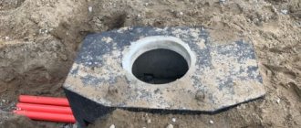
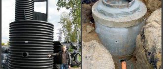
Appearance of plastic cable wells
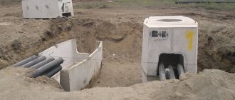
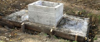
Reinforced concrete wells
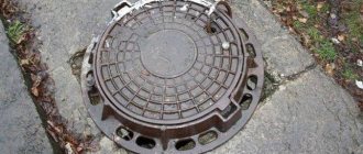
The products consist of two parts - upper and lower. There is a window at the top for installing a hatch. The shape of the wells is made round, square or in the form of a prism.
Concrete is prepared with fine aggregates to ensure water resistance and water resistance. The product may contain a hydrophobic coating to protect against groundwater. The structure is reinforced with a frame made of steel mesh or reinforcement, which is assembled by spot welding.
The container is equipped with pipes for cable entry. They are connected to cable sleeves using compression couplings, rubber cuffs or extrusion welding.
Advantages and disadvantages of plastic and concrete products
Reinforced concrete communication manifolds have been tested for decades and have undeniable advantages:
- Durability.
- Strength. The structures of concrete products can withstand heavy loads and are therefore suitable for installation under roadways. Easily withstand pressure coming from soil and groundwater.
- Big sizes. Thanks to production technology, it is possible to create tanks with large volumes.
- High frost resistance. Manufacturers claim up to -93 °C. Concrete structures can easily withstand a large number of cycles of temperature reduction to sub-zero temperatures and its increase.
Every item has its shortcomings. Concrete KKS have the following:
- High price. The basis of the tanks is cement, which is an expensive element. Fittings also increase the price of the product. Energy tariffs required for production also affect the final cost.
- Large mass. Complicates the transportation and installation of the product.
- Hygroscopicity. Concrete is not a very good waterproofer. If there is high humidity, fungi or mold may appear inside the container, which can damage cable networks or equipment.
The polymer cable well does not have the above-mentioned disadvantages. Its advantages are:
- High tightness. Thanks to this property, it has good protection against moisture. Some manufacturers offer special models for installation under the lawn. The containers have drainage and additional protection against accidental ingress of water.
- Light weight. PVC materials are lightweight, which greatly facilitates transportation and installation, which can even be done independently.
- High resistance to chemical reagents. Thanks to this property, they are suitable for different soils, including those with a high salt content.
- Plastic. Polyethylene allows you to create any shape.
- Low price. PVC structures rarely have a high cost.
It is necessary to take into account the characteristics of the plastic, as they may differ. A quality product has a passport indicating its properties.
Disadvantages of plastic cable manholes:
- Little weight. Paradoxically, dignity can become a disadvantage. When there are large vertical loads (for example, from transport) and shallow groundwater depths, it is necessary to anchor the well. This event entails the call of special equipment and the cost of a concrete foundation.
- Plastic cables are not able to fully replace reinforced concrete ones for installing power cables in large quantities. Thus, for citywide networks or engineering routes of industrial enterprises, PVC structures are not able to satisfy the needs for the number of channels and the required layout of couplings.
- Lack of standards. At the moment, the regulatory framework is insufficient for the widespread installation of polymer containers.
Plastic cable manholes
The benefits of plastic are driving the proliferation of sewer pits for electrical and telecommunications networks. Depending on the design, each type has its own marking.
- KKT-1 – well for telephone communications. Manufactured primarily for the private sector. The strength of the body is ensured by stiffening ribs.
- CODE – well for quick access. It is intended for installation of optical highways. The well contains couplings. The polyethylene structure contains distribution pipes on all walls.
- KKTM is a small-sized well for low-pair communications. Used as a container or as a manhole.
The low weight of plastic structures greatly simplifies their installation. A foundation slab is installed at the bottom, to which the container is attached with a cable or anchor. Installation is done manually. Backfilling is done with a mixture of sand and cement.
Functional purpose of the KKS
Functionally, the well is an inspection device that provides access to communication network equipment located in the ground for routine inspections, routine maintenance and repairs, as well as dismantling and laying new wired and telecommunication lines.
To ensure stable operation of communication systems, the inspection device must provide simple and convenient access for prompt identification and troubleshooting. The kit must include devices that allow quick replacement of cables.
A device placed under the road surface must be of sufficient strength to ensure the safety of network infrastructure elements under the load created by wheeled and rail vehicles on the roadway. Inspection wells placed in pedestrian areas must have a safety margin that ensures the integrity of the structure in the event of a collision with special equipment on a wheeled or tracked chassis.
A prerequisite is the frost resistance of the structure, as well as the protection of the equipment placed in it from electrochemical corrosion, exposure to sand and dirt. Increased demands are also placed on the durability of the structure and its resistance to lateral mechanical impacts associated with soil displacement.
Which well is better
While reinforced concrete wells with asbestos-cement pipes can work reliably and for a long time in harsh conditions, plastic wells do not always withstand them. The main reasons are unreliable pipe connections.
The SKTB-TOMASS company tried to introduce innovative ideas for the introduction of plastic wells in 2005. She developed the design of the PKK-2U-M1 brand made of polyethylene, documentation and mastered its own production. The device contains an internal steel frame and must be closed from above with a concrete slab with a hatch resting on the ground. Only in this case can the structure be a substitute for concrete.
Modern manufacturers of plastic wells know practically nothing about this design and more than ten years of experience in its operation. In all the lines of manufactured models it is impossible to find a single design that continues the work of the PKK well. Outwardly they seem convenient, but in fact they sell barrels, septic tanks and tanks, etc. containers made of plastic. The instructions say nothing about their flammability, the effect of hot asphalt, or the possibility of repair when the neck is demolished by a bulldozer. We are not impressed by the modest size of plastic containers, which cannot compete with concrete products for multi-pair sewers. The lightness of the structure has become a disadvantage since it requires support and anchor plates and specially fitted molds. All this increases the cost of the well.
Plastic consoles and brackets glued to the walls are not nearly as reliable as elements of reinforced concrete wells made of metal. It is impossible to install couplings in many plastic wells, and if they do manage to be “stuffed”, the bending radii of the cables become completely unacceptable.
When installing a lightweight polymer container, for greater reliability, you have to mount a sarcophagus made of a concrete slab with a cast-iron hatch on top, and install another one below as an anchor.
2.3.125
*. In places saturated with underground communications, it is allowed to construct semi-through tunnels with a height reduced in comparison with that provided in the table. 2.3.1, but not less than 1.5 m, subject to the following requirements: the voltage of the cable lines should not be higher than 10 kV; the length of the tunnel should be no more than 100 m; the remaining distances must correspond to those given in the table. 2.3.1; There should be exits or hatches at the ends of the tunnel.
___________________
* Agreed with the Central Committee of the trade union of power plant and electrical industry workers.
Features of laying cable ducts
The laying of cable channels is carried out according to certain rules.
- The pipes are buried to a depth of 40-200 cm. Plastic pipes are laid at the minimum depth, and cement-based pipes are laid the deepest. Any pipelines that require the greatest depth are laid under tram tracks. At a medium depth, pipes are installed under roads, at a minimum depth - under pedestrian areas.
- The channels are made with a slope of 4 mm/m, so that the water that gets there does not linger, but flows down.
- Pipes between wells are always located in a straight line. The permissible displacement is no more than 10 mm/m.
- In the basements of houses or in large collectors, it is advisable to lay cables not in pipes, but on consoles.
- Wires with the lowest voltage are laid to the shallowest depth.
- The optimal pipe diameter for the cable is considered to be 100 mm.
- It is not allowed to lay telephone and electrical wires in a common pipe.
- The volume of the well is selected depending on the location and purpose.
2.3.122
The need for the use and scope of automatic stationary means of detecting and extinguishing fires in cable structures must be determined on the basis of departmental documents approved in the prescribed manner.
Fire hydrants must be installed in the immediate vicinity of the entrance, hatches and ventilation shafts (within a radius of no more than 25 m). For overpasses and galleries, fire hydrants must be located in such a way that the distance from any point on the axis of the route of the overpass and gallery of the nearest hydrant does not exceed 100 m.
Construction of a manhole
Cable wells are no different in appearance from waste wells, which are containers with a bottom and a hatch on top. The hatch can be with or without a neck. For pipes with cables, holes are provided during manufacture or holes are made in the walls of the housing. Most designs contain double hatches, where the inner one is equipped with a special secret lock.
The type of well depends on the position in the network:
- pass-through - installed on straight sections or in other places where deviations reach 30°;
- station - located next to buildings;
- rotary – placed at the point where the network turns;
- dividing – in places where a line branches into several lines.
The dimensions of the well must make it possible to work with the cable and install equipment. The material is often plastic with stiffeners.
2.3.124
Laying of control cables is allowed in bundles on trays and in multilayers in metal boxes, subject to the following conditions:
1. The outer diameter of the cable bundle must be no more than 100mm.
2. The height of the layers in one box should not exceed 150 mm.
3. Only cables with the same type of sheath should be laid in bundles and multilayers.
4. Fastening of cables in bundles, multilayered in boxes, cable bundles to trays should be done in such a way that deformation of the cable sheaths under the influence of its own weight and fastening devices is prevented.
5. For fire safety purposes, fire barrier belts must be installed inside the boxes: in vertical sections - at a distance of no more than 20 m, as well as when passing through the ceiling; in horizontal sections - when passing through partitions.
6. In each direction of the cable route, a reserve capacity of at least 15% of the total capacity of the boxes should be provided.
Laying power cables in bundles and multi-layers is prohibited.
Cable duct installation
Cables are laid by professionals, since installation errors result in problems in the operation of electrical networks and communication lines. The work includes a sequence of actions.
- Drawing up a design drawing indicating all other communications located next to or at intersections with the cable installation site.
- Terrain marking.
- Making a pit for a well with dimensions 40 cm wider than the dimensions of the container. A sand cushion is made at the bottom, which should be thoroughly compacted. In flooded areas, the bottom of the pit is cemented.
- In accordance with the markings, trenches are dug with a slope for cable pipes. When other communications are located nearby, the work is done manually. The crumbling soil is secured with wooden sheets with spacers. The bottom is covered with sand or filled with a layer of concrete.
- A well is installed at the bottom of the pit at a level. The holes in the walls must correspond to the places where the pipes are laid for the cables. The container is attached to a concrete base. It may be provided with a loading chamber, which is filled with cement.
- Pipes are laid in the trenches at a distance of 20-25 cm. The free space is filled with soil. The top layer of pipes is separated from the bottom layer with a thickness of 25 cm. The soil is compacted around the pipes with a wooden shovel.
- The joints between the well and the pipes are sealed. The final backfilling of the well is done with a mixture of soil and sand, with compaction every 0.2 m.
- Wires are pulled into cable channels. Their tension should be controlled so that it does not exceed the norm. Particular attention is paid to laying the fiber optic cable.
Functions
First you need to know the functions that this structure performs. After all, it can be telephone wells, cable ducts or ducts, through which the cable is laid and subsequently power is supplied. Let's see what functions the cable communication and power supply well has:
- Installation of such a structure allows access to installed conductors, without the need for excavation work. To check the wires, detect a break in a timely manner or make repairs, you do not need to dig a trench. You just need to lift the well hatch and go down into the well.
- Today, cable wells for communication have a fairly spacious internal chamber; equipment that is not needed for work can be placed in it.
Based on the above, they are used during the laying of any communication.
2.3.126
Oil-filled low-pressure cables must be mounted on metal structures in such a way that the possibility of forming closed magnetic circuits around the cables is excluded; The distance between the fastening points should be no more than 1 m.
Steel pipelines of high-pressure oil-filled cable lines can be laid on supports or suspended on hangers; the distance between supports or hangers is determined by the line design. In addition, pipelines must be fixed on fixed supports to prevent the occurrence of temperature deformations in the pipelines under operating conditions.
The loads taken by the supports from the weight of the pipeline should not lead to any movement or destruction of the support foundations. The number of these supports and their locations are determined by the project.
Mechanical supports and fastenings of branching devices on high-pressure lines must prevent swinging of branching pipes and the formation of closed magnetic circuits around them, and insulating gaskets must be provided in places where supports are fastened or touched.
2.3.133
The laying of cables in collectors, technological galleries and along technological overpasses is carried out in accordance with the requirements of SNiP Gosstroy of Russia.
The shortest clear distances from cable racks and galleries to buildings and structures must correspond to those given in Table 2.3.2.
The intersection of cable racks and galleries with overhead power lines, intra-factory railways and roads, fire passages, cable cars, overhead communication and radio lines and pipelines is recommended to be performed at an angle of at least 30°.
