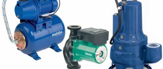
A vortex pump is a device whose task is to pump water from wells, reservoirs and storage tanks. Equipment of this type is used in conditions where it is necessary to create high pressure of liquid with relatively small volumes. At the same time, the composition of the pumped liquid should not contain chemical impurities.
Vortex pump - device and principle of operation
The high-pressure vortex pump has a fairly simple design.
The main part of its device is an impeller equipped with blades. It is located in a durable housing and is fixed on the shaft. There is a gap between the body and the wheel, no more than 0.2 mm wide. The main difference between these pumps and axial units is the method of supplying fluid inside the casing. In vortex devices, liquid is supplied along the line of contact with the impeller. This design of the vortex pump makes it easier to operate and repair.
The operating principle of the device is to rotate the wheel along with the liquid. The sucked water is affected by the centrifugal force of rotation and the suction force that is generated in the grooves. Thanks to centrifugal force, the liquid is directed towards the periphery of the blades. As a result, a vacuum is formed in the grooves, due to which suction force appears. When it suppresses the centrifugal force, the water begins to move towards the wheel.
This procedure is repeated until the impact forces become equal. As a result, a vortex appears on each of the blades, which increases the pressure. Despite the rather complex principle of operation, the design of a vortex pump is extremely simple.
Operating rules
The described unit is installed on a hard surface strictly horizontally and, if possible, closer to the source of water intake. In case of vibrations, it is also advisable to secure the structure with a metal frame or bolted frames. The pump is connected to the network through the RCD fuse block. Grounding can be provided with a steel wire about 6 mm thick. In this case, one end of it is attached to the body, and the other to a ground electrode in the form of a metal pipe from a well or any structure leading into the ground.
Next, you can begin direct operation of the vortex pump, checking its tightness and the correctness of the connections made. First, the suction pipe and pump part are filled with liquid. To do this, you can use a funnel and a filler outlet in the structure. When the pumping part is completely filled, you can put the equipment into operation.
Advantages and disadvantages of vortex equipment
Vortex water pumps have several advantages. These include:
- Lower cost compared to other types of equipment;
- Simple design;
- Ability to independently absorb water;
- Possibility of use in liquid-gas mixtures.
Units of this type also have a number of certain disadvantages. Firstly, they have low efficiency - on average it does not exceed 45%. This indicator does not allow vortex pumps to operate at consistently high power. Secondly, the pumps cannot cope with pumping high-viscosity liquids.
Varieties
Vortex type pumping equipment can be divided into two types:
- open-vortex units;
- closed vortex pumps.
Their operating principle is slightly different, since the first type of pumps have:
- extended impeller blades;
- reduced diameter of the impeller in comparison with the clearance of the working channel;
- the annular channel in the device is connected to the pressure hole.
Closed-vortex units have the following structure:
Design and principle of operation of a plunger pump
- shortened blades installed at different angles of inclination (tilt forward, bend back, or at a certain angle back or forward);
- the diameter of the impeller is equal to the clearance of the working channel;
- the annular channel has a direct connection with the inlet and outlet.
The principle of operation is different for each variety. During operation of the open-vortex unit, water from the inlet pipe enters the annular channel through the inlet and the working chamber with the impeller. Here, the working vortex process contributes to the formation of a pressure flow. This flow is directed through the outlet into the main pipeline.
In closed-vortex type units, the aqueous medium from the suction pipe penetrates through the inlet into the annular channel. Here a pressure flow is formed and directed through the outlet into the main pipeline.
Classification of units by method of action
Depending on the mode of action, vortex pumps can be of the following types:
- Reciprocating - in such units, fluid circulation is carried out by moving a piston located in the cylinder. On sale you can find reciprocating vortex pumps, both with a piston and with a membrane;
- Rotary - in these devices a piston displaces water. Based on the type of working body, such pumps are divided into roller, screw, vane and gear pumps;
- Dynamic - in these pumps, the movement of liquid is carried out as a result of the transfer of kinetic energy to it.
Each of the listed types of units has found application in specific areas. They differ from each other in design and dimensions.
Hello student
Dynamic pumps
Of the dynamic ones, vane and jet pumps are most widely used on ships.
Centrifugal pumps
In vane pumps, the movement of the pumped liquid is carried out as a result of the rotation of the impeller with blades. According to the nature of the effect on the fluid flow, they are divided into centrifugal, vortex and axial. In the first, the fluid flow moves from the center to the periphery in the radial direction, in the second - vortex-like along the annular periphery, in the third - along the axis of rotation of the blades. The design diagram and operating principle of centrifugal pumps are discussed above (see Fig. 60). The most widely used on ships are centrifugal vane pumps, which cannot perform dry suction, i.e. start when there is no liquid in the suction cavity. Therefore, before starting, these pumps are filled with the pumped liquid; water pumps are installed below the waterline. However, compared to other pumps, they are less sensitive to fluid contamination, provide uniform supply and constant pressure in the line under steady-state operating conditions, and can be activated by any drive without a gearbox. Depending on the location of the working shaft, centrifugal pumps are divided into vertical and horizontal. Based on the flow rate, pumps are distinguished between low (up to 20 m3/h), medium (21 - 60 m3/h) and high (more than 60 m3/h) flow pumps; by pressure value - low-pressure with an outlet pressure of up to 0.5 MPa, medium-pressure with a pressure from 0.5 to 5 MPa and high-pressure with a pressure of over 5 MPa; Based on the method of supplying liquid to the wheel, they are divided into pumps with one-way and two-way liquid supply, and based on the number of impellers - into single-stage (with one wheel on the shaft) and multi-stage. Single-stage K-type pumps with a cantilever impeller arrangement and an angular contact bearing that absorbs axial force during pump operation are widely used on ships; double-acting type D with liquid supply to the impeller on both sides, relieving it from axial forces; single- and multi-stage pumps with vertical and horizontal axes of impellers, non-self-priming (NTsV, NTsG) and self-priming (NTsVS). Multistage pumps can have impellers connected in series or in parallel.
When the wheels of multistage pumps are turned on in series, the liquid, leaving the first wheel, is supplied to the second, etc. In this case, the pump flow as a whole will be equal to the flow of one wheel. However, the pump pressure doubles, triples, etc., in proportion to the number of stages.
When the pumped liquid from individual pump impellers (when they are connected in parallel) enters a common line, the pump pressure does not increase, it is equal to the pressure of one wheel, but the pump flow increases in proportion to the number of wheels included in the circuit. Multistage pumps are used as drainage pumps on rescue ships, fire pumps on large-capacity ships, cargo ships, tankers, i.e., where a large flow is required with a relatively low pressure. The diagram of a multi-stage fire pump type DPZHN is shown in Fig. 144. Two impellers 1 and 4 are installed on pump shaft 5. Liquid enters the pump through pipe 6 and is pumped into the main line through pipe 2. When valves 7.3 are moved to the position shown in Fig. 144a, the pump operates with parallel wheels, and when the taps are switched to the position shown in Fig. 144.6 - according to a sequential connection scheme. In the first case, the pump has an outlet pressure of 9.8 MPa and a flow of 100 m3/h, in the second - 19.6 MPa and 50 m3/h, respectively.
Vortex pumps
Vortex pumps are a type of vane pumps (see Fig. 61). They are usually used for relatively small ranges of flows and pressures. One of the most common are self-priming vortex pumps of the VKS type. The operation of vortex pumps is based on the principle of vortex formation, which creates the possibility of suction of liquid with the direction of flow along the axis of rotation of the wheel. Vortex pumps can pump liquids and their emulsions with air or vapors of these liquids. Despite the low efficiency, horizontal electric driven centrifugal vortex self-priming pumps of the ESN type used on river vessels when pumping water provide a supply of 3–12 m3/h at a pressure of 12–44 m and a self-priming height of up to 5 m. For the first start of the pump, its body is filled with water .
Rice. 144. Multistage centrifugal pump
Subsequently, the water remaining in the housing ensures self-priming of the pump during startup.
Self-priming centrifugal vortex pumps of the TsVS type are most widely used as cargo pumps in the river fleet. In the housing of such pumps, two wheels are mounted on a common shaft. The pumped liquid flows first to the wheel of a centrifugal pump, and then through a special channel to the wheel of a vortex pump. When the unit is started, the impeller of the vortex pump sucks air from the inlet pipe and discharges it into a special pipeline, and then, having created the necessary vacuum in the inlet pipe, both wheels pump the liquid into the discharge line.
Axial pumps
In accordance with the state standard, axial pumps (they are also called propeller or axial) are produced by industry in two modifications; OV - axial vertical with rigidly fixed impeller blades; OPV - axial vertical with manual rotation of the blades. Depending on the shaft location, these pumps can be inclined or horizontal. They differ from centrifugal ones in the design of the impeller and the profile of the blades that move the pumped liquid in the axial direction. The impeller 8 (Fig. 145) of the OB type pump is mounted on the shaft console 5 and installed in a cylindrical housing 3. Ring 7 protects the housing from cavitation damage. The pump shaft is protected by a fairing 4 and rotates in bearings 2 with brass liners coated with rubber. The suction pipe 9 of the pump has guide ribs to prevent water from swirling during suction. The main and emergency 1 (for emergency pumping out of water) flanges are located on the branch pipe. When the wheel 8 rotates, the liquid is transferred by the blades along the axis and, leaving the impeller, falls on the blades of the guide vane 6, where, as a result of a decrease in speed, the dynamic pressure of the liquid is converted into static pressure, due to which its pressure increases.
Rice. 145. Axial pump
With a head of 10–25 m and an efficiency of 90–92%, axial pumps develop a flow rate of up to 3000 m3/h or more; they are used in ballast systems of transport ships and floating docks, as drainage devices, in water-jet propulsion-steering devices, as well as thrusters ships.
Jet pumps
Jet pumps have become widespread on ships, the operating principle of which is to convert the energy of a jet of steam or water passing through a nozzle into a diffuser. Based on the type of working fluid, such pumps are divided into steam and water jet. In the first, suction and injection are carried out using the energy of moving steam, in the second - the energy of water. When jet pumps are connected to the object being served by a suction pipe, they are called ejectors, and when connected to the object by a discharge pipe, they are called injectors.
On modern river vessels, water-jet ejectors are widely used (Fig. 146). The working fluid (water from a fire main or from a pneumatic tank) is supplied to the ejector through nozzle 3. When leaving the nozzle at high speed, water enters diffuser 2. Passing through the narrowing section of the diffuser, water carries along air and creates a vacuum in the mixing chamber, due to whereby the pumped liquid is sucked into pipe 1. The reverse transformation of energy occurs in the expanding part of the diffuser. Here, the speed of movement of the mixture of working and pumped fluids (their kinetic energy) decreases and the static pressure (pressure) in the discharge line connected to the diffuser flange increases.
Injectors and ejectors differ from other pumps in the absence of moving parts, the ability to pump contaminated liquid and good suction ability. However, due to low efficiency (3-15%) and the impossibility of regulating the flow, they are used only in short-term systems, where simplicity of design is crucial. On river vessels, jet pumps are used as vacuum devices to remove air from large centrifugal pumps before they are started (for example, dredge pumps). Jet pumps are also used on tankers to create pressure in the suction line of cargo pumps. Most widely, jet pumps (ejectors) are used in drainage systems to remove water from compartments, and injectors are used as feed agents for steam boilers.
Rice. 146. Ejector
Positive displacement pumps
In positive displacement pumps, the pressure difference between suction and discharge is created by a moving working element that changes the volume of working fluid in the pump chamber. During suction, the volume of the chamber increases, and during discharge, it decreases. Depending on the type of working body, volumetric pumps are divided into piston (plunger) and rotary (gear, screw, axial and radial piston, vane).
Piston pumps
The main parts of a piston pump are a cylinder and a working body in the form of a piston or plunger (see Fig. 34, 42). With the reciprocating movement of the piston (plunger) in the cylinder cavity, either a vacuum necessary for sucking in the liquid or an excess pressure is created, due to which the liquid is supplied to the discharge pipeline. The pistons (plungers) of the pumps are driven through a crank mechanism connected to the electric motor shaft, or through an eccentric or cam drive of a diesel engine. Based on the number of cylinders, pumps can be single-, double-, or multi-cylinder, and based on their location, they can be vertical, horizontal, or inclined. Pumps in which liquid is supplied to the discharge pipeline only when the piston moves in one direction are called single-acting pumps. In double-acting pumps, in any direction of piston movement in the cylinder, both suction and injection of liquid occur. All plunger pumps operate unilaterally and are characterized by large uneven flow. In plunger pumps, the cylinder diameter is significantly less than the stroke of the plunger and the rod is practically an extension of the piston. Due to this feature in the piston design, plunger pumps create fairly high pressures in the discharge lines. On ships they are mainly used to supply fuel to diesel injectors (see Fig. 42).
Along with the unlimited possibility of creating high discharge pressure, piston pumps can regulate the flow without changing. pressure, they are easy to maintain, have a fairly high efficiency, and have the ability to dry suction, i.e., they can practically suck in liquid when it is completely absent from the suction line. However, piston pumps are very bulky, have a large mass, do not provide uniform flow, are slow-moving, and require the most complex means to ensure their automatic control. Therefore, piston pumps are used where the indicated disadvantages do not play a significant role, but it is necessary to ensure high suction capacity of the pump or to achieve high pressure in the discharge line. Due to the reduction of steam vessels and increasing requirements for flow, weight and overall dimensions of pumps, the scope of application of piston pumps in the river fleet has somewhat narrowed in recent years. They are used mainly as reserve manually operated ones in fuel pumping, lubrication, cooling systems of diesel engines, in bilge and other ship systems.
For pumping water and oil products on ships, double-acting piston hand pumps of the HP type are widely used. Two valve boxes with suction valves I, 9 and discharge valves 2, 8 are attached to the pump housing 12 (Fig. 147) with suction 11 and discharge 5 pipes. In the horizontal cylinder 3 of the pump, using the handle 6, you can move the figured rod 7, at the ends of which two pistons 4 and 10 are mounted.
Rice. 147. HP manual piston pump
When the handle moves to the left, the pistons move to the right. The liquid enters the left cavity of the cylinder through the open suction valve 1, and from the right cavity through the open discharge valve 8 and pipe 5 is forced into the discharge pipeline. When the direction of movement of the handle changes, the liquid will be sucked into the right cavity of the cylinder and forced out of the left.
Gear pumps
Unlike piston pumps, in rotary pumps of the gear type, the change in volume in the working cavity, which ensures suction and injection of liquid, is carried out by rotors (gears) rotating in the housing.
Reversible and non-reversible pumps in terms of the number of gears can be single-stage (single-section), two-section and multi-section (with several pairs of gears), in the shape of the teeth - spur, helical, chevron, and depending on the nature of the gear meshing - involute, cycloidal and trapezoidal.
The most widely used on ships are gear pumps with a pair of spur gears of external gearing and the same number of teeth of an involute profile. Pumps of this type are distinguished by their simplicity of design, are very reliable in operation, and have good suction capacity. Therefore, despite the low efficiency (33-45%), they are widely used as diesel-mounted and electric-drive pumps for pumping petroleum products with low pressure and flow. For the river fleet, gear (rotor-gear) pumps of the RZ type are supplied, having a flow of 1.1–5 m3/h, a pressure of 0.33–1.45 MPa, a shaft rotation speed of 1450 min-1 and an electric motor power of up to 2.8 kW . Pumps of types Sh - with internal supports on feet, ShF - with internal flange supports, ShV - with outriggers on feet, ShG - with internal supports and heating (cooling), ShVG - with outriggers and heating (cooling) - have also received significant use. . Pumps of these types are supplied for river fleets with a flow rate of up to 38 m3/h, pressure of up to 3.5 MPa, shaft rotation speed of 1000 and 1450 rpm, power of up to 14 kW.
Liquid ring pumps
To create a vacuum in closed containers, liquid ring pumps are used along with jet pumps. They are classified as positive displacement pumps, in which a change in the volume of the working chamber is achieved by shifting the position of the inner surface of the liquid ring relative to the rotor blades. The pump (Fig. 148) consists of a cylindrical body 1 with 3 suction and 4 discharge pipes. Rotor 2 is eccentrically mounted inside the housing. Water is poured into the pump housing. As the rotor blades rotate, they throw water toward the walls of the housing, forming a rotating water ring. The crescent-shaped space between the inner surface of the water ring and the rotor hub constitutes the working chamber of the pump. If the rotor rotates counterclockwise, then the surfaces of the water ring on the left, as shown in Fig. 148, move away from the cavity a of the chamber.
Rice. 148. Water ring vacuum pump VVN
The free volume that forms between the rotor blades is filled with air through pipe 3, and through cavity 6 of the chamber it is pumped into pipe 4.
Screw pumps
Of all positive displacement pumps, screw pumps provide the most uniform flow.
According to the number of rotors (screws), they can be one-, two-, three- and multi-screw; in the direction of liquid flow - single-flow (with one-way suction) and double-flow (with two-way suction); depending on the direction of rotation of the screws - reversible and non-reversible, and according to the location of the housing - vertical and horizontal. Screw pumps are used on tankers of projects 866, 868, R 42, oil pumping stations NPS 120, NPS 612 and other vessels. The design of one of these horizontal pumps with double suction is shown in Fig. 149. The pump has a screw with a rectangular tooth profile in the right and left directions. When screw 2 rotates, liquid flows through gear 1 into the side suction cavities a and into the pump housing 3, and through cavity b it is pumped into the main line. Screw pumps are used for pumping clean and contaminated, including aggressive liquids.
Rice. 149. Single screw pump
In the latter case, they are performed with an autonomous lubrication system and remote bearings hermetically separated from the cavities a and b. Of the multi-screw pumps for pumping petroleum products on ships, horizontal double-suction pumps BC 200 are most widely used. They have three screws, each of which, like the single-screw pump considered, is made with a right-hand thread on one half and a left-hand thread on the other. The middle screw is the leading one, and the other two are the driven ones. BC 200 pumps pump 200 m3/h of fuel at a pressure of 2.5 MPa and a suction height of up to 6 m.
Rotary piston pumps. In positive displacement pumps of this type, cylinders with pistons perform reciprocating motion. Depending on the location of the cylinders relative to the axis of the block, they are divided into radial piston and axial piston. For the former, the cylinders are located radially, and for the latter, they are parallel to the axis of rotation of the block. On river vessels, axial piston pumps are mainly used as part of the hydraulic drives of steering machines (see Fig. 130).
Rotary vane pumps
In the technical literature, such pumps are also called rotary lobe and vane pumps. Liquid is supplied to them (see Fig. 36) by transferring it in the cavities between the retractable plates of the rotor, which rotates eccentrically in the pump housing. Rotary vane pumps are included in the systems of some diesel engines and are used at oil pumping stations to unload too viscous petroleum products.
Marine fans. Fans and compressors are used to move gases (mostly air on ships). Fans include devices with a working body in the form of a blade wheel designed to move air with an excess pressure of no more than 0.015 MPa.
Rice. 150. Axial and radial fans
Vane and piston pumps of various designs, pumping air with a pressure of more than 0.015 MPa, are classified, as indicated, as compressors.
Fans are widely used on ships to create comfortable conditions in residential and office spaces, as blowers for boiler installations, for ventilation of machinery spaces and cargo holds. By purpose, ship fans are divided into injection (pressure) and exhaust, connected by a suction pipe to the service object, and by design - into axial and radial (centrifugal), vertical and horizontal. Depending on the supply pressure, low (up to 0.001 MPa), medium (0.001 to 0.003 MPa) and high (over 0.003 MPa) pressure fans are distinguished. Low and medium pressure fans are used on river vessels. To create low pressure, axial fans are usually used; for medium pressure, centrifugal fans are used.
Based on the principle of operation, fans are similar to vane pumps, but have a more simplified design. An electric motor 7 is mounted in the housing 4 (Fig. 150, a) of an electric axial fan (EVO), on the shaft 6 of which an impeller 2 with blades 5 is mounted. A front fairing 1 is installed in front of the impeller, and a rear fairing 9 is installed behind the electric motor. When the impeller rotates, air enters pipe 3 and is pumped into the main line along the axis of the shaft through the expanding rear part of the housing 8. Axial fans create low pressures, and on ships they are used to supply air to holds, living and service spaces. Fans are produced in series, each of which includes several different sized, but practically similar fans. Each fan size is assigned a number equal to the outer diameter in decimeters.
In radial (centrifugal) type fans (Fig. 150, b), when the electric motor 5 is running, the impeller 1, rotating together with the shaft 4, sucks in air through the inlet pipe 2 and moves it into the housing 3 along a radius from the center to the periphery. For radial marine fans with the PC index, the blades can be bent forward or backward in the direction of rotation; There are also fans with straight radial blades. Fans with forward-curved blades develop greater pressure, but have lower efficiency than fans with backward-curved blades. Therefore, to increase efficiency at low pressure, fans are usually made with blades curved backwards in the direction of rotation of the wheel. On river vessels, two types of radial fans are used: with the indices RSS (radial ship with a spiral casing) and RSC (with a cylindrical casing), supplying 25-400 m3/h of air at a pressure of up to 0.0098 MPa. Artificial ventilation on ships is carried out using electric fans, and their local and remote activation (from the wheelhouse) is provided. The operating mode of the fans is regulated by throttling the suction air by changing the position of the louvers (control dampers).
Rules for servicing ship system mechanisms
The operating features of each type of pump are outlined in the relevant instructions.
Before starting pumps, like any other mechanisms, they are inspected externally to determine the reliability of fastening the pumps to the foundation, the serviceability of ballasts and instrumentation, the quality of seal packing, and the presence of lubricating oil in bearings and other rubbing parts. Before switching on, non-self-priming pumps are filled with the pumped liquid by opening the valve on the suction pipe and the air valve on the pump body. Valves, taps and other fittings may only be opened and closed using standard handles and handwheels.
The specified operating mode of the pumps is set according to instrumentation readings. If the readings of pressure gauges and vacuum gauges differ from the specified values, the pump is stopped and the tightness of the suction and discharge lines is checked. The flow and pressure of drive pumps are regulated by changing the speed of the engine shaft or by artificially increasing the resistance in the discharge pipeline. At a constant speed of the drive motor shaft, the flow is controlled by changing the opening of the bypass valve.
During operation of the pumps, make sure that there are no knocks and noises that are not typical for normal operation of the systems, regularly check the reliability of the lubricating devices and the degree of heating of the rubbing parts, pay attention to the tightness of the gland seals and pipeline connections, and eliminate possible air leaks; monitor the instrument readings.
It is prohibited to: troubleshoot pump parts while they are operating; disassemble and open pumps, tanks, fittings and pipelines that are under pressure or filled with hot liquid; inspect and repair system elements in tanks and rooms where accumulation of harmful gases is possible, without preliminary analysis of air samples for gas contamination.
The pumps are stopped in the following order: close the valve (cock) on the suction line, stop the electric motor, and then shut off the discharge pipeline. To ensure better suction, the valve on the receiving line of centrifugal pumps is closed last.
Maintenance of inactive pumps consists of eliminating defects found during their operation and maintaining all system elements in constant readiness for operation.
Literature used: “Ship power plants” by V.A. Sizykh
Download abstract: You do not have access to download files from our server. HOW TO DOWNLOAD HERE
Archive password: privetstudent.com
Separation of pumps according to the type of arteries and wheels
Depending on the location of the waterway, the following types of vortex pumps can be found on sale:
- Units with open artery:
- Pumps with a closed water artery.
According to the types of impellers, pumps are divided into:
- Open wheel equipment;
- Devices with a closed wheel.
Closed-type pumps are equipped with short blades. Liquid suction is carried out through a special pipe. Such units have a low cavitation rate. Due to the joining of the longitudinal vortex and the liquid substance, the rate of movement of the water at the inlet slows down slightly. In order to increase the cavitation properties, a centrifugal stage is connected in front of the vortex wheel. Such equipment is called centrifugal-vortex. These units have a slightly higher efficiency than vortex pumps, about 48%. Devices of this kind are widely used for water supply systems and boiler power supply.
Units with an open wheel differ from devices of the previous type by the longer blades. Due to this, their cavitation rates are an order of magnitude higher, which allows them to be used for pumping wastewater in industry and utilities.
Nowadays, many manufacturers combine the properties and advantages of several types of equipment in pumps. Thanks to this, on the modern market you can find vacuum, air and thermal vortex pumps. The main difference between these devices lies in the technical characteristics and areas of application. Units of the first type are successfully used in the chemical industry for working with gaseous substances. Thermal devices have found application in providing liquid to various steam power plants. Air vortex pumps are used to maintain the operation of deep industrial water wells.
Areas of application of vortex pumps
It is quite difficult to imagine modern industry without pumping equipment. Vortex pumps were no exception. Today they are used in the following industries:
- To maintain the operation of boiler stations;
- For pumping liquids containing gaseous components;
- To supply water to rural water stations;
- For the operation of automobile service stations;
- As elements of compressor units;
- For the purpose of pumping alkalis and acids.
Smooth operation in all these industries requires pumps to withstand mechanical damage, aggressive chemicals and wear.
Vortex or centrifugal pump - which is better?
In order to understand which is better - a centrifugal or vortex pump, you should decide on several factors - areas of application and characteristics of the units. Centrifugal pumps can be used to pump clean water or water containing small impurities from ponds no more than 9 meters deep. During operation, such devices create a small pressure, consume a significant amount of electricity and have quite large dimensions.
The main difference between a vortex pump and a centrifugal pump is that units of the first type create greater pressure while having the same power. They are smaller in size and consume much less electricity. In addition, vortex pumps can pump liquids containing gases.
For comparison, it is also important to note the disadvantages of vortex pumps, which centrifugal devices do not have. The main one is the instability of vortex units to frequent mechanical damage. In contrast, centrifugal pumps are made of cast iron, which can withstand shock easily.
When comparing units of both types, it is quite difficult to determine the best one.
We can only note that if the buyer does not need high pressure and wants to pump out dirty water, then you can purchase a durable centrifugal pump, which, moreover, will operate much quieter. If you need to achieve maximum pressure, then it is better to purchase a vortex unit - it produces more noise, but costs an order of magnitude cheaper. We should also not forget that manufacturers constantly combine the properties of different types of pumps. Today it is very easy to purchase a centrifugal vortex pump that will have all the properties and advantages of the units we are comparing.