In a water supply or heating system, it is necessary to maintain a given direction of fluid flow. If you allow fluid to flow in the opposite direction, a difference in pressure may occur, which leads to water hammer and damages devices connected to the pipeline. The liquid should also not return through the pump back into the well. To ensure all this, a check valve must be installed in the system.
A check valve is necessary in the water supply and heating system.
What is it and what is it for?
A water back pressure valve is a shut-off valve that ensures coolant flow in only one direction and prevents its outflow in the opposite direction. This is a necessary element in the design of any water supply and heating system, as it maintains optimal pressure and protects the hydraulic system from sudden surges in fluid pressure. This device works only due to the energy of the working fluid, i.e. operates in autonomous mode.
Sometimes, due to a leak in the pipeline, the water pressure decreases. This can happen if the pumping equipment malfunctions. In this case, the valve installed in the system prevents the outflow of water into the well, and after troubleshooting, the entire system will not need to be refilled with water.
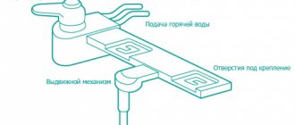
Connecting a solenoid valve to a garden watering system
For a small garden, a -12 volt solenoid valve for irrigation (NT8048) is better suited. It is safe because if water gets on the contacts or if you touch it with wet hands, there will be no electric shock. The ability to connect it to a 15 Ah battery allows you to work without recharging for a week. It will also be easy to supply power from the shield via an AC adapter.
The water supply is provided from a storage tank installed at a height of at least 2 m. The water in it is drawn from a centralized system. Filling is controlled by a float sensor connected to a plug valve. The absence of a pump eliminates many problems. Watering the garden by gravity occurs within a few hours and does not need to be controlled. All irrigation control will be taken over by an electronic timer connected to the outlet.
The valve is installed in the pressure line of the irrigation system. The electromagnet coil is connected to the output of the adapter via a cable using terminals. They can be sealed on top with sealant to protect them from water.
The entire device can be conveniently placed in a utility room where you can install an outlet. A timer, adapter and electromagnet coil are connected in series to it. All that remains is to configure the watering mode. The time is chosen in the morning and evening so that there is a minimum of evaporation and the plants do not get sunburned. The duration of watering is set, which is then selected experimentally.
Watering should be different for different types of plants. The system can be gradually improved by adding new valves. You can connect your own timer to each of them or install a common microcontroller, setting the irrigation program.
Valves from old washing machines can be installed on the outlet pipelines, which will allow you to save a lot on the cost of the irrigation system.
Purpose and scope of application
The key purpose of a check valve is to protect the pump from damage. When the pump is not working, water can return to the well again, spinning the pump impeller in the opposite direction, which contributes to wear and tear of the pump. And with shut-off equipment installed, water cannot flow back into the well, since the valve plate closes under the action of a spring.
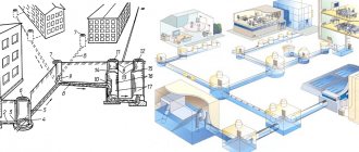
It is recommended to install the valve in the following locations:
- In front of the water heater. The water heated in the boiler has high pressure and can return to the pipeline. However, a valve installed in front of it prevents this.
- On metering devices. Constant pressure surges in the flowing fluid can damage measuring instruments. A valve installed on the meter will help protect it from damage. This device also prevents the meter impeller from rotating in the opposite direction.
- After the submersible pump. Autonomous water supply systems involve the installation of a submersible pump in a well. A valve installed after the pumping equipment prevents the outflow of liquid from the system back into the well if for some reason the pump stops working.
Installation in front of the water heater Installation of the valve on metering devices Installation after the submersible pump
Application area
Here are just a few examples of the use of check valves in private and municipal water supply, heating and sewerage systems:
- It happens that due to pressure surges in the water supply (including from the pump), hot water is squeezed through cold water. That is, when you open a cold water tap, hot water flows for some time. In this case, installation of a check valve on the cold supply pipe is indicated.
- The device installed before the water pump will prevent water from draining into the well, and will also protect the equipment from damage in the event of reverse spinning of the working blades.
- In front of the water meter. The water pressure and vibration that is created can harm devices and distort meter readings. Vibration does not spread after the shut-off valves.
- Double-circuit gas (solid fuel or other boilers) must also be equipped with an appropriate valve to prevent the return of already heated water.
- Solar collector. Here, circulation disturbances may be associated with a small difference in the temperature of the liquid at the inlet and outlet, or a slight difference in height (if the water heater is small). It would be a good idea to equip the solar water heater inlet pipe with anti-reverse protection.
- Drainage pumps begin their work by filling the device with water. Many owners find this procedure tedious and come up with ways to avoid it. To prevent water from pouring out of the unit, a valve is placed on the suction hose.
- Where groundwater rises strongly, it is important to install a check valve on the pipe connecting the drainage pit and the house so that when the liquid level rises, it does not flow back.
In some of the listed cases, installing a valve is desirable, while in others (such as with a boiler) it is mandatory and is specified in the accompanying documentation.
Controls and technical characteristics
Check valves are controlled automatically using the energy of the working medium. When purchasing a device, you need to pay attention to the following technical characteristics:
- Nominal diameter (DN) - diameter of the nominal diameter of the connecting pipe. This value applies when installing the valve to the pipeline.
- Nominal pressure (PN) is a value indicating the highest pressure of the working medium at a temperature of 20ºC, under which the device can operate uninterruptedly.
- The throughput coefficient (Kvs) is a value numerically equal to the volumetric amount of water passing through a fully open valve at a pressure difference of 1 bar. The throughput coefficient is measured in cubic meters and is used to calculate head losses.
- The valve opening pressure is a value numerically equal to the difference in liquid pressure before and after the device, at which the valve is fully opened.
Possible difficulties
In the process of self-production, home craftsmen face a number of difficulties:
- Incorrect calculation of downforce. The spring has to be shortened or, more unpleasantly, wound again. This problem is usually solved by selection.
- Insufficient quality of surface treatment of the seat. The valve does not press against it completely and allows water to pass through. Solved by grinding the surface.
- The flow resistance is too high for the specific system conditions. I can’t decide whether I’ll have to choose a different type of valve or buy an industrial one.
Making a check valve yourself will be a good test of your engineering and plumbing skills.
Connection type
The locking device can be mounted in one of the following ways:
- With a flange connection type, the valve is connected to the section of the pipeline between the disks of two pipe flanges using fasteners and an O-ring. The advantage of this method is the ease and simplicity of disassembly in case you need to replace parts or repair a breakdown.
- With the coupling type of connection, the fittings are connected to the pipe using a fine-pitch thread located on the inside of the pipe. The outer side is shaped like a hexagon so that you can use a key. The advantage of this type of connection is that there is no need to use additional fasteners; among the disadvantages, one can note the laborious process of screwing the pipe onto the pipeline.
- With the wafer type of connection, the fittings are clamped between the flanges at the ends of the pipe sections. This connection has a high level of tightness.
- With a welded connection, the fitting pipes are mounted into the system by welding. This method is used in cases where the working medium is poisonous gases or liquids, since the welded connection ensures complete tightness of the system.
Installation of water back pressure valves
The material for stamping elements of the prefabricated body is brass. The alloy is resistant to aggressive substances (oxygen, mineral salts, sulfur, manganese, iron compounds, organics, etc.) that are dissolved or suspended in water. The outer surface of the product is galvanized (nickel-plated).
The spool parts are made of copper-zinc alloy or high-strength polymer. The material of the sealing gasket between the locking discs is rubber or silicone. The spring is made of a special grade of stainless steel.
Design of a polypropylene spring check valve: 1 - body, 2 - plug, 3 - embedded part with thread, 4 - rod with spool plate, 5 - spool washer, 6 - spring, 7 - plug sealing ring
Common design elements of spring check valves:
- composite body (coupling connection elements with internal threads at the inlet and outlet, spool chamber);
- working body - a movable spool, consisting of a rod, two spool plates and a sealed inter-disk gasket;
- the actuator of the lock is a spring, which is located between the valve plates and the seat (the limiter in the body of the body).
The working body of the check valve performs reciprocating movements in the spool chamber. The plates slide along the spool rod. The flow is distributed through a channel that has a constant cross-section. Water evenly washes the locking organ from all sides.
If the flow pressure exceeds the resistance of the spring, then the movable part of the valve opens a gap for the passage of water in a given direction. When the excess pressure equalizes before and after the protective device, or the set pressure after the valve exceeds, the spring moves the poppets into the seat.
To install an autonomous water supply, you will need a check valve, ball valve, pressure gauge, fittings and other components
Spring coupling check valve
The collapsible cylindrical body consists of two parts with a threaded connection. The movable spool is formed from a plastic rod, upper and lower brass plate. The valve elements are separated by a hermetic sealing gasket. The tension of the steel spring counteracts the flow pressure through the spool poppet mechanism.
Spring coupling check valve, with brass spool
A distinctive feature of a water check valve device with a spherical spool chamber is its high throughput compared to traditionally shaped fittings.
Design of a spring check valve with a brass spool: 1 and 2 - nickel-plated brass body, 3 - movable spool, 4 - spring, 5 - brass spool plates, 6 - EPDM gasket
Combination spring check valve with drain and air vent
A pipe with internal thread for the air vent is installed on the housing, above the receiving area of the spool chamber. The air is released using a Mayevsky tap.
The drain pipe with internal thread and plug is located on the opposite side of the housing, at the outlet of the check valve.
When mounted vertically, the device allows draining water after the valve and removing air pockets from the pipeline before the valve. When installing the combined device horizontally, the air removal pipe is used to install a pressure gauge.
A combined check valve reduces the number of installation connections, reduces the total hydraulic resistance of the fittings, increases the reliability of the system, and facilitates the process of installation and maintenance of the system.
Check valve with drain and air vent
Spring check valve with polypropylene body
Check valves in a propylene body are used for water supply systems made of propylene pipes. Externally, the fitting is similar to an oblique bend. Protective fittings made of propylene are attached to the pipeline using polyfusion welding. For ease of maintenance of the non-separable connection, the seat and the shut-off spool mechanism are moved out of the perpendicular plane of the spool chamber. The design position allows the valve locking mechanism to be removed for cleaning and repair, without compromising the integrity of the body and system.
In main pipelines of centralized water supply, petal, disc, flap, ball and wafer check valves are used. To connect large-diameter fittings, flanges and wafer fastenings on tie rods are used. To install check valves in piping made of propylene pipes, contact heat welding is used.
Spring check valve made of polypropylene
Device
The design of the device includes the following elements:
Valve device.
- Metal body.
- Pipeline connection areas. Depending on the type of connection, they can take different forms.
- A plate with a rod that acts as a damper.
- A spring that promotes automatic closing of the damper when the pressure decreases.
- Sealing tape that helps ensure a secure fit of the plate on the seat.
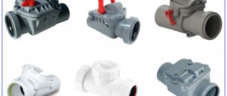
Types and designs
Depending on the type of working elements and the method of fastening, spring, petal, ball and lifting types of valve designs are distinguished. The choice of one type or another depends on the characteristics of the pumping station, the diameter of the pipeline and the characteristics of the working fluid.
Spring coupling
In models of this type, the working element is a disk, which, in the absence of flow, is held by a spring in a position pressed against the seat. Devices of this type are easy to install and unpretentious. It is recommended to install on pipes with a cross-section of 15-200 mm, where the working fluid is water, gas or other non-aggressive coolant. The disk can move forward and backward only along the flow axis, while constantly remaining in the flow area. Due to this, the throughput of the device is reduced.
Spring clutch valve.
Rotary paddle
In petal-type devices, the working element is a steel disk, which can move radially in the presence of flow. As soon as the water supply is interrupted, the steel disc falls onto the seat under the influence of gravity. Due to this design feature, the valve should be installed only on horizontal sections of the pipe; the device will not work in a vertical position. The main advantage of this type is that the valve can operate regardless of the type of coolant or working fluid.
Ball model
The working element of a ball check valve is a heavy ball made of cast iron. With direct fluid flow, the ball moves into a chamber located outside the passage of the device. When the fluid moves back, the ball returns to its place under the influence of its own gravity, blocking the passage. These devices are distinguished by tight closure and ease of installation. They also have low requirements for the quality of the working fluid; they can even work with viscous coolants.
Lifting type product
Lift valve.
Lift valves are equipped with a plug element that, when there is no flow, is held in the “closed” position by gravity. Some manufacturers supplement the design with a spring.
Spring models can be installed in both vertical and horizontal positions. A direct flow of water presses on the valve from below, lifting it. And the reverse flow presses from above, pressing the plate even more tightly to the saddle. This blocks the reverse flow of water. The advantage of products of this type is ease of installation and unpretentiousness to the quality of the working fluid.
Use if the system is installed incorrectly
As users emphasize, the same thing happens when the slope is too steep, and the water does not have time to cope with the waste. Check valves for sewerage may be needed when the pipeline is worn out. This occurs during long-term operation of the system, within which deposits form. The clearance inside will become less and less, and provided that the flow rate is normal, coarse-grained elements will be fixed to the walls. Gradually they accumulate, become hard and form a blockage. Home craftsmen note that the need to install the described element may be required when horizontal bends are installed at right angles. These nodes change the configuration of the pipeline, as a result of which the speed of movement of the wastewater is lost. Regardless of whether it slows down or speeds up, it negatively affects the operation of the system, which causes a clog to form.
Advantages and disadvantages
The advantages of installing check valves include the following:
- Fluid flow in one direction only.
- Ease of installation and troubleshooting. If any problems occur in the device, the structure can be easily disassembled and the problem fixed.
- If the water in the house is heated by an electric device, then a shutter installed in the system will help reduce unreasonable energy costs.
One of the disadvantages is that when installing a check valve, joints and fastenings appear, which are the most vulnerable parts of the system and can leak liquid.
Selection tips and approximate price
Before you begin choosing shut-off valves, you need to determine the characteristics of the water supply or heating system. Some tips for choosing a device:
Before choosing shut-off valves, it is recommended to determine the characteristics of the water supply and heating system.
- Heating systems in which the pipelines are made of metal require the installation of a rotary valve. Metal systems will rust over time, allowing fluid to become contaminated, and butterfly valves are less susceptible to clogging.
- It is recommended to install disk devices on pipes made of metal-plastic.
- Shut-off valves made of polypropylene cannot be installed on pipes through which hot water is transmitted. Any valve with a metal body is suitable for these purposes. Polypropylene valves can be installed on cold water pipes.
Prices for locking devices vary and depend on the type of product. For example, wafer-type cast iron products from Danfoss will cost 7,500 rubles. Valtec products have the lowest prices. Devices from this manufacturer can be purchased for prices ranging from 200 to 500 rubles.
Making and installing a check valve yourself
Although the market offers a large selection of types of devices to solve certain problems, some people decide to make the valve themselves. To do this, you will need to purchase individual elements of the future product and fastening means.
Required tools and materials
To make your own ball-type shut-off valves for water, you need to prepare the necessary materials in advance:
- Tee with internal thread.
- For the valve seat, you need to take a coupling with an external thread.
- Spring made of stainless steel. It should fit into the hole freely.
- Cork. It will serve as a plug for the entire device and support for the spring.
- A steel ball, the diameter of which is slightly less than the nominal diameter of the tee.
- FUM tape.
Work progress
When all the materials are ready, you can begin the process of assembling the product. To do this, you can use the instructions below:
- First of all, screw the coupling into the tee, which will serve as a saddle for the valve element. It is necessary to screw in until the coupling covers the side hole of the tee by approximately 2 mm. This is necessary so that the ball does not jump out into the side passage.
- Through the opposite hole, a ball is first inserted, and then a spring.
- Plug the hole through which the spring was inserted. This is done using a threaded plug using sealing tape.
- Such a homemade device will allow water to flow into the side hole due to the fact that the direct flow will put pressure on the ball and the spring, and in the absence of flow, the ball will block the passage, returning to its original position under the action of the spring.
When making the device yourself, it is recommended to correctly adjust the spring. It should not deviate when the pressure in the system is low, and should not be too tight so as not to interfere with the normal flow of fluid.
Rules for installation and operation of the device
There are a number of rules and recommendations that must be followed when carrying out installation work:
- Using a valve, turn off the water supply completely or only at the installation site.
- Devices in which the operating element comes to the closed position due to gravity should be mounted in a horizontal position. On vertical pipelines, such devices will only work if water moves through the pipeline from bottom to top. All other types of valves can be fixed to both horizontal and vertical pipes.
- The arrow on the device body must coincide with the direction of water movement.
- It is recommended to install a mesh filter in front of the device, which will trap debris present in the liquid.
- In order to be able to diagnose the condition of the device in the future, a pressure gauge can be attached to the outlet of the device.
- It is not recommended to destroy the paint coating on the device body, as it performs a protective function.
Connection diagram
In heating and water supply systems, the choice of location for installing the valve is determined by those areas where water or coolant flow is required in only one direction, and the hydraulic features of the system can lead to fluid flow in the opposite direction. These shut-off valves should be installed in accordance with all regulatory requirements. The following connection diagrams exist:
- If the system contains several pumps installed in parallel to each other, then the valve should be mounted on the connecting pipe of each pump. This is done to prevent water from flowing in the opposite direction through a failed pump.
- If heat flow sensors or water consumption meters are installed in the system, then a valve should be installed on their pipes. The absence of a shutter can cause water to flow in the opposite direction through the meters, which will lead to improper operation of these meters and incorrect readings.
- In heating systems with a common heat supply center, the device must be installed in the mixing units on the jumper. If this is not done, the coolant may pass from the supply pipe to the return pipe, bypassing the heating system.
- In a heating system, the valve is installed in the area through which the coolant flows from the heating device to the heating device, if there is a possibility of a pressure drop in this area. This will help prevent the backflow of water from the pipeline when the pressure in the external network drops. In this case, on the return section it is necessary to install a pressure reducer that operates on the “toward” principle.
Connection diagram.
Tools
To make devices, you will need the following tools and equipment, which are probably available in every self-respecting home workshop:
- Desk or workbench.
- Vise or massive clamp.
- Hacksaw for metal.
- Drill or benchtop drill press.
- Pliers.
- Assembly knife.
- Set of files and needle files.
- Sandpaper of different grits.
- Jigsaw (electric).
Different materials and components are required for different designs and will be listed in the appropriate section.
Frequent errors and problems during installation
The valve may fail due to errors and shortcomings during its installation. Therefore, it is recommended to follow the instructions specified in the description during the installation process. It is necessary to carry out a technical inspection of the device at least once a month to identify problems. When operating shut-off valves, the following problems may arise:
- If during installation you forgot to remove the plug or valve lock, then there may be a lack of flow. A plug remaining in the tee can cause the pressure in the area before the valve to be less than the pressure in the area after it. This results in the device being unable to pass liquid. To eliminate this malfunction, it is recommended to dismantle the structure and remove the plug.
- In contaminated water, solid mechanical particles can damage the valve or get stuck between the seat and the plate. This leads to the fact that the valve will not seal the passage. To fix this problem, you need to dismantle the device, carry out cleaning procedures and reinstall it. Before doing this, it is recommended to try to wash off this particle with a stream of water. To do this, you can close and open the shut-off valve closest to the valve several times.
- An unsuccessfully selected valve leads to knocking noise. This happens due to the larger valve diameter. This problem can only be solved by purchasing a new device with a smaller diameter or reinstalling the existing one in a more suitable location on the pipeline. Please note that knocking may also occur due to the fact that the device is installed too close to the central pump. High flow turbulence also contributes to tapping in the device.
- A broken threaded coupling is another consequence of non-compliance with instructions during the installation process. This occurs if the valve is under stress from the pipelines, or if too much sealing material was used during its installation. In this case, it is recommended to replace the device.
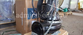
Air diaphragm valve.
The device is a membrane valve (valve) with a forced opening function.
1. When air spontaneously moves from the apartment into the ventilation shaft, the valve flaps open under air pressure.
2. When air from the ventilation shaft begins to move into the apartment, the valve flaps slam shut and the valve is hermetically sealed.
3. In order to ensure ventilation of the room in case of excess pressure in the ventilation shaft, an exhaust fan is used.
Using this simple pattern, I built the first air valve. An EDG-2K motor with a power of only 5 Watts from an antique tape recorder was used as a motor for a homemade fan.
The first fan model revealed a number of shortcomings. With high air pressure in the mine, the 5-watt engine could not provide normal ventilation. And the seals on this engine were not of a very good design, which is why the bearings had to be lubricated too often. Unfortunately, this homemade fan has not survived, so I cannot present it.
At the first opportunity, I replaced the homemade fan with a factory-made instrument fan VN-2 with a power of 20 Watts. In those days, they just had to be repaired, and some of them ended up as “dry residue”.
By luck, the diameter of the homemade fan almost coincided with the diameter of the VN-2, and the valve did not have to be redone. I just drilled four new mounting holes and sealed the old ones with tape.
Everything would have worked like that, but one day my wife went to the neighbors living on the floor below just when the fan was running. When she returned, she reported that the neighbors heard the noise from our propeller several times louder than ours, although their apartment was not even located below us, and we did not have a common ventilation pipe with them. This is the acoustic paradox.
I assume that this was partly due to the fact that the shaft of the VN-2 fan rotated in ball bearings, and the fan itself was not isolated by shock absorbers, and partly, perhaps, with some unknown resonance phenomena in the ventilation system.
One way or another, it was decided to seriously improve this design.
This is what happened as a result.
Expert advice
To avoid installation errors and further troubles, it is recommended that you familiarize yourself with the advice of experts:
- Pay attention to the arrow indicated on the valve body. The direction of this arrow must coincide with the direction of fluid flow in the pipeline.
- The device must be installed in places where there is easy access. This is done so that technical inspections of the product or repair work can be carried out in the future.
- Before proceeding with installation, it is necessary to check the device for leaks.
- Steel and brass appliances have a long service life, as they are highly resistant to high pressure and corrosion. Therefore, it is recommended to purchase devices made from these materials for water pipes.
- If the house uses autonomous heating, the valve should be installed in the return pipe at the outlet of the heating device.
- The valve should be installed after the metering devices so that the reverse flow of water does not distort their readings.
- If a plastic device is intended for installation in a system of cast iron pipes, then it is necessary to install an adapter from cast iron to plastic.
A valve correctly installed in the water supply or heating system will help avoid many troubles. In order for it to function for a long time and correctly, you must follow the advice of specialists and follow the installation rules specified in the instructions.