When drawing up a project for an external drainage network, it must include a sheet “table of sewer wells”. It displays all the wells, grouped into groups. They are listed indicating the operating parameters, in increasing order of the diameter of the pipes or trays.
For each unit, the main operating parameters, dimensions, depth of immersion in the ground, volume of the working part, and the amount of material spent on manufacturing are displayed. As a result, a complete list of containers accepted for a given system appears and are grouped by purpose and type.
What it is
The sewer well table is an appendix to the sewerage system design. It consists of several tables compiled for wells of different types and purposes. All capacities that are available in the network profile are grouped by type:
- linear (KSL, Linear Observation Well);
- rotary (KSP);
- nodal (KSU), etc.
If the number of containers is small, you can create one table in which the parameters of all groups, listed in ascending order, are indicated one by one. As a rule, this is the tank number, depth and diameter of the pipes. Example of a finished table:
A typical sewer well is a structure with standard dimensions. They vary depending on the number and size of incoming (and outgoing) pipes, purpose, availability of additional devices and equipment. Using this concept allows you to speed up the process of drawing up a project, since the task of separately calculating each structure is removed. For each type of structure there is its own table, compiled separately for plastic, reinforced concrete, brick (stone) containers.
SNiP requirements
The main requirements of SNiP include the following:
Scheme of wells made of concrete rings according to SNiP
- the well must be sealed. The presence of a drainage layer instead of a bottom is possible only with a daily waste volume of up to 1 m3;
- the well must be located on the site, taking into account the minimum distance to all its objects specified in the same document;
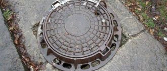
- the well must be equipped with a lid to prevent the spread of odors throughout the area and the entry of debris into the structure;
- the depth of the well cannot exceed 3 meters.
Sewage well location diagram
As for the location of the sewer well in relation to other structures located on the site, it should be like this:
- at least 5 meters from a residential building;
- more than 1 meter from outbuildings;
- at least 2 meters from the neighbor’s fence;
- 30 meters from a well or well with drinking water;
- 3 meters from the road.
If these parameters are not met, the project will not be approved by the SES.
Regulations
The table of sewer wells is compiled on the basis of current standards and rules (SNiP, SP). These are basic documents that list all the requirements for the design of containers, their sizes and other parameters. Any inconsistencies discovered during the defense are regarded as grounds for project rejection.
However, if you use only basic regulatory documents, the risk of making mistakes increases. For each tank you will have to select parameters separately, which will significantly slow down the preparation of the project. The structure of SNiP or SP is designed to list rules, requirements and standards. It is inconvenient for carrying out design work, so a special database has been created to help compilers - the Standard Project (TP). Currently, a more modern edition is used - TPR (Typical Design Solutions), which is a revised version of the database.
Sewer wells, Standard Project is a set of tables for different groups of containers. They are united by purpose, size, and features. The designer’s job is to select the desired option based on the values given in the columns.
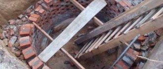
Start of construction of a sewer well
First of all, it is important to design a sewer system that will run on the territory of a private house. It goes without saying that if you do not have enough experience or time to draw up such a project, then you can take ready-made plans that are found in specialized books or on the Internet. A high-quality plan involves not only pipe lines and trenches, but there should also be an estimate for the building materials that will be needed for the construction of the entire system. Using such an estimate, you can save a significant amount of money, even if the amount of building materials is exceeded by 20%.
If you are planning sewer wells yourself, you need to know about the successive stages of this work.
- The first step is to decide on the location of the well. This should be a flat surface that is slightly below the level of the house. This arrangement will help facilitate the installation of pipes, and will also prevent blockages in the system in the future and make draining easier.
- The location for the well must be chosen taking into account the position of the house. You need to choose a location to minimize the number of pipes and thereby save money. If there is an error in the location, there is a chance to simply lead all the pipes around the house, and only then pull them to the well, which requires a lot of money.
- Once the exact location of the sewer well has been determined, the entire project needs to be moved to scale. This will allow you to make calculations and understand approximately how many pipes will be needed to construct the entire system, as well as where to dig trenches, install a toilet and allocate space for waste.
a ready-made plan in your hands , according to which you can safely purchase the required amount of building materials and start working.
Table items
In the table, you can separately consider each sewer well, the design of which is no longer needed separately. Each column indicates certain parameters of the structure. The first contains the node number according to the plan, the second determines the soil conditions. They are designated by Roman numerals:
- I - dry soil, not capable of subsidence;
- II - wet soil (in Russia this is the main type);
- III - subsidence soils.
The remaining columns show the size or type of individual nodes. Most of the values are needed for excavation work (diameter and depth of the tank), and are also necessary for calculating the amount of materials.
The depth of the structure is its total height from the bottom of the tray (or the bottom of the pipe) to the manhole cover. According to current standards, the manhole cover is located flush with the asphalt surface, 5-7 cm above the soil if the well is located on a lawn, or 50 cm above the soil in a forested area.
The height of the working part and neck is taken according to the pipe laying conditions. They depend on the depth of soil freezing and on the profile of the drainage network, distance from the starting point, slope, etc.
The depth of the tray is selected in accordance with TP “sewage wells” 902-09-22.84. It is usually taken to be 100 mm larger than the diameter of the largest pipe entering the container.
The brand of the well is also determined according to TP 902-09-22.84. To do this, the type of container, its size and other parameters are taken into account. Based on the tables given in the TP, a suitable option is selected, for which the types of standard structures are indicated in a separate column. The type of hatch (light, small, etc.) and the type of stepladder for lowering or exiting workers are also noted here.
Also read: Do-it-yourself drainage from sewer pipes - drainage system, features, review
Volumes of tank elements
The volume of the well is determined according to the TP tables. For public sewerage networks, this parameter is not important, since it is not taken into account anywhere. Only other values are considered - height, diameter, etc. However, sometimes volume is important. For example, instead of performing complex calculations, you can accept wet sewer wells using TP. These are reservoirs where temporary storage of wastewater is carried out. Wet wells include:
- storm water intake wells;
- storage tanks in private homes;
- drainage tanks, etc.
For such structures, volume plays an important role, since the amount of waste is expressed in appropriate units.
The height of the pipe drop is needed only for drop wells, since in other structures a “shelyga to shelyga” connection is used.
The volume of concrete per tray is determined by the TP, but sometimes you have to count it manually. This is necessary if non-standard well elements are used. Knowing the amount of material, you can immediately calculate the total volumes of building materials for building the system. There is no point in calculating each well separately; the project allows you to immediately determine the full volume of concrete or other materials for all structures. This significantly speeds up the process of preparing working documentation and also allows you to avoid errors or inconsistencies.
How to calculate volume
One of the main indicators is the volume of the sewer well.
It must be calculated so that no problems arise during the operation of the structure, for example, too rapid filling.
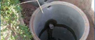
Calculation of the volume of a sewer well made of rings
If we talk about a storage well, then the volume is calculated using a very simple formula: V=n*q*15, where:
- V – volume of the sewer well;
- n – number of people permanently residing in the house;
- q – volume of water in liters. Per day per person;
- 15 – service interval for the sewage disposal machine, in days.
For example, you need to calculate the volume of a well for a family of 3 people. Then we get the following: 3*200*15=9000 liters or 9 m3.
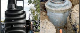
Septic tank made of reinforced concrete rings for 9 cubic meters
If we talk about the volume of a drainage well or septic tank, then instead of 15 in the formula you need to put the number 3. This is how long the wastewater coming from the sewer system is processed through the natural processes of rotting and fermentation.
Types and characteristics of concrete rings
Reinforced concrete rings in accordance with GOST 8020-90 are made of concrete grades M200 or M500, using reinforcement with a diameter of up to 10 mm, made of steel class At-IIIC, At-IVC (GOST 10884) and A-I, A-II, A-III ( GOST 5781), as well as BP-I wire (GOST 6727), with a cross-section of at least 0.6 mm. In everyday life, when constructing sewer wells, the following types of rings and auxiliary elements are used:
KS - wall rings in accordance with GOST 8020-90 have an internal diameter from 700 to 2500 mm, a height from 290 to 1190 mm, the thickness of their walls is in the range from 70 to 100 mm. Products are produced both with smooth ends and with protrusions for installation with a locking connection. It is allowed to increase the dimensions of concrete rings for sewerage in height in increments of 300 mm up to a value of 1790 mm.
Rice. 6 Parameters of PP floor slabs
KO - support rings installed on top of the structure to create a low neck, which is then covered with a hatch. Concrete rings for KO sewerage specified in the standard have a single standard size with an internal diameter of 580 mm, a wall thickness of 130 mm and a height of 70 mm.
In contrast to the requirements of GOST 8020-90, commercial companies supply the market with a wide range of support rings of various sizes (they are also called additional rings), many of them are used for installing high necks intended for organizing manholes into chambers. Some products have a more complex configuration with an expanded support part and a narrowed neck.
KCP - rings with a poured overlap on top, have a round or rectangular opening of standard sizes for penetration into the chamber.
KCD is a concrete ring with a bottom for sewerage, has the dimensions of a standard KS, convenient for constructing caisson wells, septic tanks, closed settling tanks, underground sealed tanks (cellars, vegetable stores).
PN and PP - bottom slab PN (too often you can find its incorrect designation PD (according to GOST 8020-90 PD is a rectangular road slab with a hole)) and the upper floor slab PP, which has a round or rectangular hole offset to the edge.
According to GOST 8020-90, PN slabs are produced in three standard sizes with outer diameters of 1500, 2000 and 2500 mm and thicknesses of 100 and 120 mm. The symbol indicates the internal diameter of the wells in decimeters under which they are placed - PN 10, PN 15 and PN 20.
PP floor slabs with holes have standardized internal dimensions, designed to cover wells with diameters from 1000 to 2500 mm, their external dimensions range from 1160 to 2700 mm. The width of round manholes is 700 and 1000 mm.
PO – square support plate with dimensions 1700x1700 mm, thickness 150 mm and a hole with a diameter of 1000 mm.
Rice. 7 Price list 2021 for well reinforced concrete products