Of all the methods of placing wires, laying the cable in the sewer is considered the most reliable. This is an underground installation method in which the cable is placed in its own channel. An extensive network emerges, which is a complex engineering system.
It requires constant maintenance, status monitoring, and connection restoration. It is impossible to lay a continuous line. The cable has to be divided into parts and laid in separate channels connected in series. This is a time-consuming and demanding task that affects the communication and supply of energy to buildings, urban areas or entire settlements. Let's take a closer look at it.
Definition, purpose and types of telephone sewer
Telephone cable duct
I would like to start with the fact that telephone sewers are buried structures, which are organized by laying pipes and installing wells.
To be more precise, this is a whole system of underground structures designed to carry cables through them.
The most important purpose of this type of sewer network is to properly protect wires (lead and plastic types) from mechanical damage.
The most important feature of such a pipeline is that there is no need to dig up the soil to protect or repair cables.
Moreover, modern wires laid in telephone sewers are simpler than those located directly in the ground (they are armored).
There are two types of telephone sewer:
- distribution - channels are attached directly to racks, buildings, distribution cabinets, as well as to cable poles. In order for the installation to be competent and there is the possibility of further repairs on the site, special wells are made;
Distribution cable duct
- main - is that a stationary well is installed, and from it there is a branching in different directions. Moreover, each of them must be attached to the distribution cabinet. This type usually includes pulling additional and main cables.
Main cable drainage
Cable duct functions
- Protection of wires from atmospheric agents, soil and road loads, etc.
- Possibility of replacing, repairing, branching electrical or telephone networks without opening the soil or destroying the road surface.
Types of cable sewer systems
The most common classification of cable sewers is based on the method of laying sewer pipelines.
- Installation of pipes can be carried out in pre-prepared trenches. In this case, the soil is removed.
- Trenchless installation allows, when running the cable underground, not to violate the integrity of the soil surface. This installation is carried out using horizontal drilling.
Cable sewers also differ in the shape and cross-sectional size of the wells and pipes themselves, as well as the material from which the sewer elements are made.
You may be interested in information - inspection well
Wells can be reinforced concrete, brick or plastic. Pipes made of plastic, asbestos, concrete, fiberglass, pitch fiber and steel are used for cable ducting. The most common are asbestos or plastic. Sometimes, instead of pipes, special plastic blocks with several sections are used - multichannels.
Multichannels connected to each other
Types of pipes used
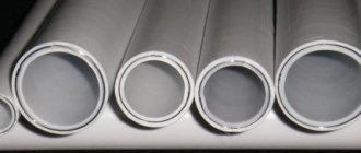
In previous years, underground installation was carried out using steel and asbestos cement pipes. Now they have added products made from different types of plastic:
- polyvinyl chloride;
- polypropylene;
- high pressure polyethylene;
- low density polyethylene.
The use of each type is regulated by regulatory documents - GOST and SNiP. For example, only a control cable is allowed to be laid underground in a steel casing, since the power cable with such installation has no protection in the event of a breakdown.
Steel pipes today are used for wiring inside buildings Source wirings-diagram.com
Asbestos-cement pipes are almost never used these days due to their fragility and heavy weight; the use of steel pipes, which are quite expensive and subject to corrosion in a humid environment, is also limited. They were replaced by plastic, the material is lightweight, durable, non-corrosive, and has excellent dielectric properties. Plastic pipes can have different cross-sections, wall thicknesses, be smooth or corrugated, single- or double-layer.
Communication cable wells
These structures are installed at intervals of 25 to 150 meters from one another. There are KKS (communication cable wells) made of bricks or reinforced concrete. Their size depends on the number of channels carried through them. Typically, standard prefabricated or reinforced concrete solid structures are installed. KKS come in standard or standard design. According to their design features they are divided into:
- walk-through (also called straight) - they are installed in areas where the installation of cable ducts is implemented without turns or when the angle of deviation of the route from the center is no more than 30 degrees;
- corner;
- branching - they are placed in the places of inlet or outlet of channels;
- station - they are located near buildings where cable equipment is located.
KKS are distinguished regarding the load on them:
- for roadways - 80 tons;
- for pedestrian areas - 10 tons.
Wells can also be rectangular, have many sides, etc. According to the sizes they are made small, medium and large.
Cable inspection wells
The design solution of the KKS assumes the presence of two compartments - lower and upper. Straight wells have through holes at the ends for placing packages. Before installing the well in the desired location, a pit is prepared. When the device is mounted, proceed to placing the hatch. Typically, the kit includes two covers: the top one is made of cast iron, and the bottom one is made of steel with shut-off fittings for a padlock. From the inside, on the walls of the KKS there are consoles, thanks to which the cable is laid in the sewer. When arranging cable ducts in an open version, passages through the tracks are made by puncture or using horizontal drilling. In the second case, a drill is used to make a hole for the sewer network, which, during the return process, pulls the pipe into the finished space. In some cases, in large populated areas, tunnels and sewers are built underground specifically for laying utilities. The personnel serving them have convenient access. These facilities are equipped with ventilation systems and stationary lighting fixtures.
Installation of couplings
9.1 Installation is carried out using optical couplings produced by Svyazstroydetal.
9.2 Installation is carried out in accordance with the instructions for installing optical couplings. Upon completion of installation, measure the attenuation in each fiber of the installed cable. When laying in a cable duct, the mounted coupling, together with the technological supply of the optical cable, is installed on a bracket on the wall of the cable duct.
9.3 During installation of couplings, it is necessary to avoid contact of optical fibers with an unprotected body in order to prevent injury from glass particles of optical fibers.
What do you need to know about telephone sewer design?
Designing a telephone sewer system is, perhaps, the first stage of the construction of a KKS.
The document must contain the following information:
Cable duct project
- the location of the route for laying the pipeline on the site;
- minimum number of obstacles;
- estimated costs for protecting pipes from electricity;
- the number of mechanisms that are planned to be used during installation.
The design documentation also specifies the minimum distance from railways.
Design of cable ducts near roads
SNiP provides certain requirements for the installation of telephone sewerage.
Here are some of them:
- the surface of the cable must be smooth, and the pipeline itself must be durable, frost-resistant and resistant to groundwater;
Groundwater resistant cable with smooth surface
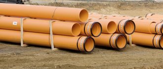
- for small-channel blocks, polyethylene pipes with a diameter of 55-58 mm are used. For other types of cable, reinforced concrete and asbestos-cement pipes with an internal cross-section of 90-100 mm are used. The pipeline must not have a harmful effect on the cable sheath;
PVC pipes 55 and 100 mm in diameter
- more than 6 optical cables of the same type are not allowed in one communication channel;
- installation of wire cores in a lead sheath should not be carried out at air temperatures below -20 degrees Celsius, and the use of material in a polyethylene sheath is allowed up to -10 degrees;
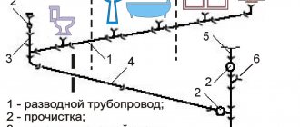
Cable duct diagram
- The input of city telephone and coaxial trunk cables is organized in the lower rows of the cable duct . In collectors, wires can be arranged in two rows, but their specific sequence must be observed. On the one hand - wire broadcasting, communications, heat pipes, and on the other - power, wire broadcasting, communications and water pipes.
Laying cable ducts
Cable laying in cable ducts can be carried out in different ways, which depend on its weight.
For example, if it is less than 1500 kg/km, then the installation can be done manually; with a weight of up to 6 thousand kg/km, a cable machine/hand winch is required; if a cable of more than 6000 kg/km is used, there is no need for a winch.
Basic regulatory documents
2.1 Guidelines for the construction of linear structures of trunk and intrazonal cable communication lines. .- M. 1986
2.2 Guidelines for the construction of local network structures. /Ministry of Communications - M. 1996.
2.3 Manual for the operation of line-cable structures of local communication networks. - M. 1998
2.4 RD 45.120-2000 Technological design standards. Urban and rural telephone networks.
2.5 R 50-601-40-93. Recommendations. Incoming control. Basic provisions. – M. 1993
2.6 Installation and electrical measurements of line-cable communication structures. KTE24-1-97. – M., 1997
2.7 Rules for commissioning communication structures. Approved by order of the Ministry of Communications 09.09.2002. – St. Petersburg: 2002
2.8 Rules for electrical installations. In the 7th edition.
2.9 RD 45.190-2001 Elementary cable section of a fiber-optic transmission line. Standard acceptance test program.
2.10 Labor protection rules when working on cable communication lines and wire broadcasting (radio) POT R O-45-005-95
Features of installation of a cable sewer system
- The depth of the cable channels depends on the material of the pipes and the installation location and can range from 40 to 200 cm. Concrete pipes are installed the deepest, while plastic pipes are laid at the smallest depth. In addition, pipelines passing under tram tracks are buried as deep as possible, under pedestrian areas at a minimum, and under highways at an average depth.
- When laying pipes, it is necessary to maintain a slope of 4 mm per meter. This allows water trapped in the channels to drain out.
- Pipes and cables in them between wells must be laid in a straight line. Only a small displacement is allowed, which should be no more than 10 mm per meter of pipe.
- Depending on the resulting cable laying pattern, inspection wells are installed every 25-150 meters.
Cable in tunnel
- Inside the basements of buildings, large sewers, etc. It is not advisable to lay cables in pipes; here the wires are pulled through special consoles.
- If several pipes are laid in a trench, then those of them in which the wires with the lowest voltage will be stretched should be closest to the surface of the earth.
- The optimal diameter of cable drainage pipes is considered to be 100 mm. In previously used pipes with a cross-section of 15 cm, cable pulling was more difficult.
- Electrical and telephone wires cannot be laid in the same pipe.
- It is necessary to choose the right manhole in terms of volume and depending on the location and function performed.
Don't miss: Installing a plank subfloor in the traditional way
Selection of pipes according to technical characteristics
The greater the depth to which the cable corrugation is laid in the ground, the greater the mechanical strength it should have. Strength depends not only on the thickness of the walls, but on their ratio to the diameter of the pipe. It is determined by dividing the outer diameter by the wall thickness and is indicated by the SDR indicator: the lower it is, the higher the reliability of the product.
Table for determining SDR Source moikolodets.ru
Design rules: norms and requirements, SP
When designing and constructing cable ducts, certain norms and rules must be observed.
Construction standards provide for the following protection methods:
- from electrochemical corrosion,
- from water and gas getting into pipelines and wells,
- from mechanical influences of the soil and ground shifts.
If possible, an impassable part of the road is selected for laying cables to avoid intersections with rail tracks and streets.
A set of design and construction rules has been developed for telecommunication systems of buildings and structures. It regulates all the necessary requirements for laying cables. The Ministry of Communications issued document VSN 116-93 to regulate departmental building standards.
Requirements for installing inspection wells:
- The distance between wells should not be more than 150 m.
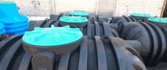
- Reinforced concrete wells, prefabricated and fully prefabricated structures are used. Wells made of other materials are used if their use is justified. Recently, ready-made plastic wells with stiffening ribs are often used, especially with a light load.
- To increase the volume, it is allowed to build new wells next to existing ones.
Requirements for laying pipelines:
- The inner surface of the pipeline must be smooth.
- The pipeline must be resistant to frost, physical stress, and waterproof.
- For distribution and main networks, polyethylene pipes with an internal diameter of 55-58 mm are used. In other cases - concrete and asbestos-cement pipes 90-100 mm, or from recycled polyethylene with an outer diameter of 63 and 110 mm.
General norms for laying cables in pipelines:
- Cables of various types can be laid in cable ducts. But no more than 5-6 cables of the same type in one pipe, and they should not occupy more than 0.75 of the channel diameter.
- Armored cables can be laid without polyethylene pipes. Unarmored ones are laid in small cross-section collectors.
- Cables of wired broadcasting networks can be laid together with communication cables if their combined voltage does not exceed 240 V, and the length of the section is controlled.
Temperature requirements:
- Work related to laying cables in a lead sheath in the open air is carried out at a temperature not lower than -20°C.
- The cable is laid in a polyethylene sheath at a temperature of -10°C.
Requirements for placement and method of laying cables:
- If the cables are located in two rows from the passage, then their sequence from top to bottom is as follows: 1 row - wire broadcast cables, communication cables, heat pipes; Row 2 - power cables, wire broadcast cables, communication cables, water pipes.
- When arranged in one row, the sequence from top to bottom is as follows: power cables, wire broadcast cables, communication cables, heat pipes, water pipes.
- Depending on the weight of the cable, a different pulling element is used: steel rope, steel wire, synthetic rope.
Application of cable with copper conductors
The use of a cable with copper conductors requires installation of a galvanic steel stocking on the sealed end of the cable.
It is made to fix the wire workpiece. The copper cable is laid using a certain technology and attached to a drum like a jack.
The cable is fed into the upper part of the drum, and there are polyethylene bushings at the entrance to the channel. The cable tension is constantly monitored.
When installation is completed, the ends are checked for leaks.
Differences between double-wall pipes and conventional pipes
On difficult sections of the route, double-walled pipes are used. They have many advantages over conventional ones.
- High ring rigidity allows it to withstand significant loads (especially for corrugated pipes).
- Despite their rigidity, double-wall pipes are flexible enough to bend around obstacles.
- Withstands temperature changes while maintaining elasticity.
- They have a nylon broach, the length of pipes in coils is from 35 to 150 m.
- The minimum bending radius is 8 diameters.
Briefly about the main thing
When thinking about electrifying a country house and outbuildings, it is worth considering the option of underground cable laying, as the most reliable, safe and durable. To ensure that communications are not exposed to the harmful effects of moisture, do not experience soil pressure, and are not accidentally damaged when digging the site, they are placed in a durable casing made of pipes. Today, HDPE pipes are considered the best, having excellent technical characteristics corresponding to operating conditions. The most critical lines are best laid in double-wall corrugated pipes.
Ratings 0
Construction of trenches
To carry out excavation work, special equipment is usually used, and in places where communications pass close, pits or trenches are dug manually, and only in the presence of employees of the organizations whose utility networks are marked on the drawings. If the soil crumbles into trenches, their walls are strengthened with spacers or special shields. The bottom of the ditches is arranged so that the pipes laid in a package are located with an inclination in the direction of the wells, which should be approximately 3-4 millimeters per meter.
Laying the pipe package
When there is a natural difference in height in the area, then the pipe package is placed at the same depth along the entire length between the inspection structures, but at a distance of ten meters from the inspection devices, the laying is done with a slope. This is necessary to insert the pipes into the well at the required height. Align the package relative to the horizon using a cord that is pulled along the side border of the ditch.
When laying the package, the pipes are placed along the trench, maintaining a distance of 20-25 millimeters between them. This free space is covered with earth and compacted. The rows of channels in the package must be separated by layers of poured and then compacted soil at least 25 millimeters thick.
The ends of asbestos-cement pipes between the devices are combined using heated polyethylene couplings or cuffs fixed with cement mortar. There is another way of joining, when a metal cuff and resin tapes are used.
If a flexible double-wall pipe for cable ducting is used, it is connected into a package by welding the joints.
Laying copper cable
Cables with a small capacity (such as distribution or intrazone copper cables) with a quantity of no more than 100 pairs are usually tightened manually. In this case, a so-called “stocking” made of galvanic steel is placed on the sealed end of the cable. The workpiece wire is attached to the sleeve or loop at the end. Cable laying is carried out in the following sequence:
- The drum with the cable to be laid must be secured on the side of the receiving device to devices (this can be trestles, carts, etc.). It is fed from the top of the drum.
- At the entrance to the hole, split polyethylene bushings or cable elbows are placed to protect the cable covering from scuffing.
- Having received the appropriate signal from the work performer, the workpiece with the cable connected to it is pulled out in the receiving structure, and at the feeding device they begin to adjust the tension of the cable coming from the drum. After completing installation in the span, the ends of the cable are checked for leaks and laid on the console. Its ends are marked with tags marked A or B.
- It is permissible to lay the cable in the sewer in winter in a polyethylene hose at a temperature of at least 10 degrees below zero, and in a lead sheath - at least minus 20.
Don't miss: Unglazed floor tiles
Laying fiber optic cable
The optical cable is laid in the sewer in the same way as is done with a copper cable. True, there are a number of technological nuances associated with the design of the optical fiber; as a result, it can be stretched over a kilometer-long segment, and in sections with turns, up to half a kilometer long. Since optical fiber is poorly affected by external mechanical loads, it is customary to protect it in sewers with polyethylene tubes with a diameter of 25-63 millimeters. They are pulled into the channel and the cable is placed directly into them. In this case, laying a fiber-optic cable in a sewer is always done using a swivel and with a device for gripping the fiber-optic cable, compensating for its stretching.
General provisions
1.1 This instruction is intended to ensure high-quality laying, installation and commissioning of optical cables produced by Incab LLC (hereinafter referred to as the optical cable).
1.2 The purpose of this instruction is to provide conditions for uninterrupted operation of the optical cable throughout its entire service life.
1.3 The instructions are mandatory for all organizations involved in the laying, installation and operation of optical cables. Organizations installing optical cable must have appropriate licenses.
Cable tightening technique
The technology for laying cables in cable ducts depends on its type. If a tunnel type of network is used, the wires are laid on brackets attached to the walls. The simplest method consists of two steps:
- a steel rope is pushed into the pipe;
- hook the cable and pull the rope, thereby pulling the cable into the pipe.
In this way, not only installation is carried out, but also cable replacement in the cable duct.
The first action is input control. This is receiving the cable, checking its parameters, measuring the length. The second step is to group the cables according to their parameters. This is necessary to combine them into a bun for styling together. Using a separate pipe for one cable is not economically viable, so they are connected in threes (this is the maximum).
Tightening is carried out using ultrasonic testing (installation of a channel blank). The connection to the rope is made so that the load falls only on the sheath and the power central element (steel conductor intended for reinforcing the wire). When tightening, torsion compensators are used to keep the cable in working condition.
Incoming control
3.1 The following is a list of recommended incoming inspection tests.
3.1.1 Quality of cable winding. Check the quality of winding of the finished cable on the receiving drum. The winding of turns should be even. The take-up drum must not have any visible damage.
3.1.2 Cable appearance. Check the appearance of the cable visually for defects.
3.1.3 Construction. Carry out cable cutting in accordance with paragraph 7 of these instructions. Check the presence of structural elements stated in the specification for the cable.
3.1.4 Total number of OBs. Check that the actual number of optical fibers matches that stated in the cable data sheet.
3.1.5 Cable marking. Check the presence and quality of markings on the cable.
3.1.6 Construction length of the cable. Check that the actual cable length corresponds to the value in the passport (by marking).
3.1.7 External diameter of the cable. Check that the actual outer diameter of the cable matches the value stated in the cable passport.
3.1.8 Attenuation coefficient. Measure the attenuation coefficient of optical fibers at wavelengths of 1310 and 1550 nm (for multimode OF at a wavelength of 1300 nm), its value should not exceed the declared value.
3.1.9 Length and integrity of the agent. The fiber length must correspond to that indicated in the passport. Integrity must not be compromised.
3.1.10 For a cable with metal armor, electrical resistance of the “armor-ground (water)” circuit GOST 3345-76
The procedure for installing cable ducts: step-by-step instructions
Cable laying work includes the following:
- The necessary calculations are made and a design drawing is drawn up. It is imperative to take into account the presence of other communications and coordinate the digging of trenches with their owners.
- After carefully marking the area, you can begin digging a pit. In this case, the width of the pit should be 40 cm greater than the width of the well. A 15 cm thick sand cushion is poured onto the bottom. If the soil in this area is characterized by a high groundwater level, the bottom is concreted.
- Special equipment is used to dig trenches, but in the case of nearby external communications, the digging is done manually. The width and length of the trenches depends on the number and material of pipes. If the soil crumbles, the walls are reinforced with sheets of wood. Pipes are laid taking into account the slope from the center of the pipe to the wells.
- Wells are installed. They must stand level on a concrete base. Wells must be freely connected to cable pipes. If there is a loading chamber, it is filled with cement.
- Pipes are laid in prepared channels. Most often these are pipe packages, which should be located at a distance of 20-25 cm from each other. The same distance should be between the underlying layers. Free spaces are filled with clean soil.
- The well is connected to the pipes, all joints are checked and sealed. Backfilling is carried out and compacted every 0.2 m.
Installation of communication cable ducting is not an easy task, and not only installation and laying of cables, but also design. Therefore, it is best if professionals do this.
Perfectly buried cable
After all the above work, you finally fill the trench with earth. To summarize the above, we can derive the formula for a perfectly buried cable. Here's what we get:
- trench depth 900mm
- sand cushion at the bottom 100-150mm
- the cable itself
- sand cushion over cable 100-150mm
- Red brick
- soil layer 200-250mm without coarse rocks
- warning tape
- residual soil layer
Each layer after laying is compacted manually or mechanically.
As a result, you get a technologically correct and “permanently” laid cable.
Sewer TV inspection
Once installation work has been completed and the sewer is in safe use, internal monitoring may become necessary.
For this purpose, special equipment is used in the form of mini-chambers that can move freely inside the pipes.
The image transmitted to the operator's monitor is saved and can be viewed at any time.
Sewer TV inspection
You may need to look at the telephone sewer system to identify any blockages that have formed, identify cracks and damage. You may also need to control illegal cutting into pipes or a banal assessment of completed construction work. Using special equipment, you can always assess the current state of the telephone sewer system and, if necessary, provide technical support without negative consequences.
The advantage of this option
Given that there are different installation methods, what are the advantages of this method? Since the pipe is round in shape, it is ideal for laying wire or cable in it. As the conductor is pushed through, it bends less frequently, requiring less effort. Such structures have a smooth turn, unlike the box, which also facilitates installation and protects the wire from breaking.
The round section can withstand more load than any other. Cables laid underground in this way will be more protected from compressive loads and surface deformation, for example, during building subsidence.
Temperature requirements for laying communication cables
Work related to laying communication cables in a lead sheath must be carried out at an ambient temperature of at least minus 20ºС. And for laying cables in a polyethylene sheath, the ambient air temperature should not be lower than minus 10ºС.
If the ambient temperature is below these indicators, then before starting work the cable must be heated on a drum or 48 hours before the start of pulling, place and keep the coil in a closed heated room at a temperature of 20 to 22.
Video description
Confirmation of how durable a corrugated pipe is is this video:
Installation features
The electrical HDPE pipe for cables in the ground has design features that distinguish it from general purpose pipes.
- For a quick, reliable and tight connection, they are equipped with special couplings without sockets.
- To pull the cable through the pipe, the products are equipped with special probes in the form of steel wire.
Couplings for joining pipe sections Source elnow.ru