Concrete storm gutters are products of a certain configuration that are widely used in the installation of sewerage systems, when laying heating mains and cable pipelines. Due to such advantages as ease of installation, high mechanical strength and resistance to various aggressive influences, low cost and availability in different sizes, using storm trays you can create any system with optimal configuration and capacity.
Concrete trays for storm drainage are used for:
- Removal of rain and melt water from territories.
- High-quality protection of various buildings and structures located below ground level from flooding.
- Maintaining soil in a dry, solid state and protecting against erosion.
- Significant increase in the service life of roads, sidewalks, blind areas and other coatings.
Where is the use of trays relevant:
- Roads, pedestrian paths, railway tracks.
- Territories of industrial enterprises, where it is important to drain water from the territories of warehouses, workshops, parking lots, and equipment locations.
- Implementation of drainage from houses, cottages, outbuildings and other private structures.
- Creation of systems in parks and squares where it is necessary to maintain the cleanliness of lawns and open areas.
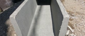
Storm gutters can be made of plastic, composite, metal, concrete. The latter option is the most preferable due to its ability to withstand any load, resistance to moisture/temperatures, ease of installation and low cost. Such trays are produced using the vibrocompression method and are dense and durable, both in a factory and at home.
Scope of application of reinforced concrete drainage trays
Concrete drainage trays
Precast concrete trays are mainly used for constructing storm sewer channels on hard surfaces. Special drainage pipes are used to drain groundwater. Reinforced concrete gutters are used for the following purposes:
- storm drainage at city facilities: parks, highways, paths;
- wastewater disposal inside industrial workshops;
- laying a cable line;
- installation of hydraulic structures;
- pipeline laying.
As a rule, concrete trays are rarely used in private construction, since the soil tends to heave during the snowmelt season. This may cause the product to shift and even break.
Storm drainage system
A storm drain (also known as a storm sewer) is a special drainage structure made up of drains, pipelines, water receivers, filters (to hold debris), inspection wells and a volumetric storage well that collects rainwater. All these elements are collected into one system and make it possible to effectively remove excess water from territories and objects, which leaves by gravity.
The collection of rain and melt water is organized where it accumulates most. Concrete sewer trays are the first link of the system, along with pipes and funnels for drainage, water inlets located under drainpipes near sidewalks, roads, platforms, etc.
Main types of storm drainage:
- Open
– the most primitive option, suitable for private plots located outside the city. Water drainage in the system is carried out using open trays/ditches; the collected water goes into the ground or reservoir.
- Closed
– involves high-quality collection/discharge of water. Closed water intakes and a system of underground pipelines are used, and inspection wells are created in the areas where fittings are installed to inspect the system. The collected water can then be used. Excavation work is expected.
- Mixed type
– a combined system for removing water along sites and roads. The trays are open, but some of the elements run underground.
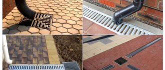
According to the type of water collection, the sewer system can be linear and cover everything (paths, platforms, roofing) or point-based with the installation of storm water inlets only under drainpipes.
What to consider when designing a system:
- The area from which water is removed.
- Average precipitation in the climate zone.
- Characteristics and properties of soil.
- Communications that pass underground.
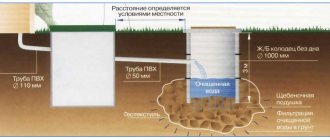
The drainage system is most often created from polyvinyl chloride sewer pipes with a diameter of 11-12 centimeters, which have sufficient strength and durability. Pipes must be installed with a slope of 5 centimeters per linear meter towards the storage tank. Storm sewer pipelines are organized in the same way as in the case of installation of household sewerage.
Inspection wells are used to maintain the system and remove blockages in a timely manner. A well is needed in both mixed and closed storm drainage systems; it is installed at the lowest point. The well accumulates and distributes/discharges water; its volume must correspond to the volume of liquid.
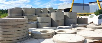
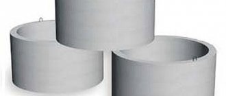
The well can be made of metal (requires mandatory waterproofing), plastic (long life, resistant to various influences), concrete (or polymer concrete). A concrete sewer storage well is the best option for a suburban area, but you need to think about its delivery and installation (the heavy weight requires the use of special equipment).
For efficient operation, the bottom of the well is made from a finished product or by pouring concrete. A cover with a hatch is mounted on top of the well.
You can make a sewer storage tank with your own hands: dig a pit, fill it with sand and crushed stone, concrete the bottom, make formwork and lay a reinforced frame in it, install pipes, concrete it, waterproof it. Then a cast iron grate is installed.
When designing a stormwater system, it is advisable to take into account the subsequent use of the collected water - for irrigation, industrial and household needs (but only after purification). Water collection trays can be plastic or metal, made of composite or concrete. Most often, a concrete tray is chosen due to its obvious operational advantages.
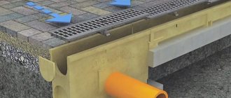
To prevent injuries and the entry of various debris into the system, install a concrete tray with a grid that protects and makes the surface of the product safe. Typically, gratings are made of metal.
Types of reinforced concrete trays
Reinforced concrete elements are classified according to the method of their installation: horizontal and vertical.
Types by purpose:
- C250. Designed for light loads. Used on small road surfaces, walking paths in the park.
- D400. They have a greater load than their predecessors. These are designed to drain storm water from busy roads and gas stations.
- E600. Used for large volumes of rainwater. More often they are installed in production and on highways.
- F900. The most powerful. Designed for storm drainage on the runway.
As for the sizes of reinforced concrete trays for storm drainage, their length is often 1 m. The internal diameter varies between 100-500 mm depending on the class of the product. The shape of reinforced concrete products is rectangular or round.
Road slabs
- GOST 21924.0-84 (1988)
Reinforced concrete slabs for covering city roads (technical conditions) - GOST 21924.2-84 (1988)
Reinforced concrete slabs with non-prestressing reinforcement for urban road surfaces - GOST 21924.3-84 (1988)
Reinforced concrete slabs for urban road surfaces, reinforcement and assembly-butt products (design and dimensions) - GOST 25912.0-91
Prestressed reinforced concrete slabs PAG for airfield pavements
Specifications
All reinforced concrete trays are produced in accordance with GOST, since high expectations are placed on them regarding strength and durability. For the manufacture of gutters, special reinforced concrete with a density of 2400 kg/m3 and cement grade M 250 are used. As a result, the finished product has the following characteristics:
- high strength to any mechanical stress, both static and dynamic;
- inertness to temperature changes;
- weight, which varies between 25-3000 kg;
- height of the gutter walls - 6-160 cm;
- waterproof;
- resistance to aggressive environments.
Due to the high mass of the product unit, it is necessary to use special equipment for installation.
Basic terminology
Drainage trays with gratings have incorporated certain formulations into their concept:
- Stormwater wells - the depth characteristics of such containers vary depending on the expected operating conditions. Such wells are mounted to storm drains;
- well for collecting sand - this container is designed to collect grains of sand, soil elements, and other solid objects. The element is made of several parts mounted into one sealed structure. Sand catchers that have one part are often used;
- waste bins are removable parts. They are classified as drainage trays and wells for collecting sand. This is where solids and debris accumulate. To remove them, the basket is removed from the well and cleaned;
- nominal value of the tray width – a design parameter, corresponds to the largest integer parameter of the tray in millimeters, taken horizontally;
- supporting tray surface - a reinforcement attachment, additional elements, and sometimes gratings are installed on it;
- reinforcing attachments - a construct necessary to protect other open-type elements from various damage likely from interaction with motor vehicles;
- contact surfaces – top of pads for reinforcement.
Installation features
Laying of reinforced concrete trays is carried out in the following sequence:
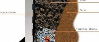
- Dig a trench of the required size. The channel parameters must exceed the dimensions of the tray by 30 cm on each side and the height. In the future, this space will be filled with a concrete pad.
- The soil at the bottom of the trench is carefully compacted and a layer of sand 10-15 cm thick is poured onto it. It is also well compacted.
- A layer of concrete mortar 15 cm thick is poured onto the bedding. It is allowed to dry completely.
- Reinforced concrete gutters are laid on the dried base using special equipment. They are joined together, all joints are treated with bitumen sealant.
- The outer sides of the trays are filled with concrete mortar.
- The drainage channel is connected to the central storm drain; the top of the gutters is covered with protective cast iron or steel gratings.
When laying reinforced concrete trays, a slight slope towards the main receiver should be maintained. Then the water will be transported by gravity.
Elements of pipe crossings
- TPR 503-7-015-90
Album 1 Round reinforced concrete culvert pipes made of long links with a hole of 1.0 1.2 1.4 1.6 for highways - TPR 503-7-015-90
Album 2 Round reinforced concrete culvert pipes made of long links with a hole of 1.0 1.2 1.4 1.6 for highways
- GOST 24547-81 (1991)
Links of reinforced concrete culverts for embankments of roads and railways (general technical conditions) - OST 35-27.1-85
Links of reinforced concrete round culverts for railways and roads
- Series 3.501.1-144
Issue 0-0 Prefabricated round reinforced concrete culvert pipes for railways and highways - Series 3.501.1-144
Issue 0-1 Prefabricated round reinforced concrete culvert pipes for railways and highways - Series 3.501.1-144
Issue 0-2 Prefabricated round reinforced concrete culvert pipes for railways and highways - Series 3.501.1-144
Issue 0-3 Prefabricated round reinforced concrete culvert pipes for railways and highways - Series 3.501.1-144
Issue 1 Working drawings, prefabricated round reinforced concrete culvert pipes for railways and highways - Series 3.501.1-144
Issue 0-4 Prefabricated round reinforced concrete culvert pipes for railways and highways - Series 3.501.1-156
Issue-0 Strengthening the channels of cones and embankment slopes of small and medium-sized bridges and culverts - Series 3.501.1-156
Issue-1 Strengthening the channels of cones and embankment slopes at small and medium-sized bridges and culverts
- Instruction VSN 32-81 for waterproofing structures of bridges and pipes on railways, highways and city roads
- SNiP 2.05.02-85 (1997)
Highways - SNiP 2.05.03-84 (as amended 1 1991)
Bridges and pipes
- Prefabricated round reinforced concrete culvert pipes for railways and highways
Advantages and disadvantages
Reinforced concrete gutters have the following positive aspects:
- High resistance of the material to aggressive environments.
- Anti-corrosion properties.
- Long service life - 50 years or more.
- Resistance of concrete to temperature changes, including the effects of sub-zero temperatures. When subjected to repeated freezing and unfreezing, the material does not lose its performance properties.
- Inertness of concrete to mechanical stress. The exception is high-power targeted strikes.
- Environmental friendliness of products. Concrete does not emit fumes harmful to the environment.
- Ideal smoothness of the inner walls due to the addition of polymers to the solution during the manufacture of trays.
The relative disadvantages of reinforced concrete gutters include their weight. However, it can also be considered a plus. Because even heaving soil will not be able to move them from their place.
Product pricing
Concrete drainage products are made from raw materials that have an acceptable cost, which influences the final pricing policy. For example, a concrete tray without a lid, small in size and light in weight, costs from 200 rubles. for a unit.
The cost is formed from the cost of raw materials, parameters, completeness, shaped differences, performance indicators for throughput capabilities and transferred load forces.
The total cost includes the quality of the product, which depends on the production equipment. A significant role in pricing is given to the cost of the grate, which can be made of cast iron, steel material or polymer composites, and have a built-in vertical drain.
Direct wholesale purchases directly from the manufacturer guarantee the lowest prices and possible discount systems. The retail price depends on the number of intermediaries participating in the “supplier-buyer” chain.
It should be remembered that when purchasing such products, it is imperative to check the documents confirming the quality of the trays.
Cost of reinforced concrete trays
Prices for reinforced concrete drainage trays depend on the size and brand. Table of approximate prices:
| Tray brand | Length of the product | Product width | Product height | Tray weight | Price, rub.) |
| L-10-5 | 1000 mm | 500 mm | 230 mm | 200 kg | 950 rub. |
| L-1-7 | 1100 mm | 390 mm | 370 mm | 150 kg | 1100 rub. |
| LV-68-30 | 680 mm | 300 mm | 340 mm | 90 kg | 1780 rub. |
| L-300 | 2950 mm | 540 mm | 430 mm | 660 mm | 3200 rub. |
The cost of reinforced concrete trays may vary slightly depending on the region and the manufacturing company.
Typical sizes
In order to clearly navigate the huge assortment of concrete drainage trays with gratings, it is recommended to correctly understand the generally accepted designations:
- D.N. This marking option was borrowed from the Germans. It shows the width of the internal gutter part in millimeters. 100 are considered European standards; 150; 200; 300; 500. Since the times of the Soviet Union, the standard values of 100 have been used in its former territory; 110; 150; 160; 200; 300; 500. Occasionally there is a marking “with a fraction”. In this case, the subsequent number marks the depth of the gutter channel in millimeters.
- L. The size of the section length, reaching from 50 cm to 3 m. There are manufacturers who produce longer structures, reaching six meters in length, or additional (shortened) elements of 50 - 70 centimeters.
- B. This letter indicates the outer width of the product. Taking into account the known DN and wall thickness, dimensions of 40 – 190 cm can be found.
- H. The depth of the product or its height. Domestic manufacturers in most cases work in parameters from 38 to 150 cm.
The manufacturer prescribes the weight of the tray with or without the grid in a metric compiled at its own discretion.
Lattices
Speaking about drainage trays, we should talk about the receiving grates that often come with them; they can be made of plastic, cast iron or steel.
Plastic products are installed on the gutters of the drainage system in places where strong mechanical loads are not expected, for example, in a park or personal plot. The advantages of plastic gratings include:
- light weight, which allows you to install it yourself;
- affordability;
- if necessary, changing the size of the product is not difficult;
- long service life.
The limitation on use is the insufficient strength of the product, which narrows the scope of application.
Grilles made of plastic
Steel gratings are stronger than their plastic counterparts, but they are much more expensive. Among the advantages of these products are the following:
- light weight, making installation and transportation easier;
- the material used is stainless steel, which has a positive effect on durability;
- excellent appearance brings a significant aesthetic component, which makes this type of grille very popular.
Stainless steel storm grates
Cast iron grates for storm drainage trays are the most durable of all types. They are installed where it is not possible to use other types due to their insufficient mechanical strength. Characteristic features of these products:
- resistance to corrosion and temperature changes;
- high mechanical strength;
- long service life.
The fairly high cost is the only drawback of cast iron structures.
Drainage cast iron grates
Purpose of the system
- Preventing the appearance of puddles and waterlogging of the area.
- Increasing the service life of road surfaces, sidewalks, foundations and blind areas of buildings.
- Protection of buried premises and structures (basements, cellars, septic tanks, etc.) from flooding.
- Reducing the degree of soil erosion.
Trays (gutters, channels) are its integral part, playing the role of linear drainage. Their function is to “receive” liquid and direct it in a certain direction to the “collection” point (for example, to a collector, roadside ditch).
There are quite a few different products designed for this. They differ in material, size, profile. To make the best choice, there are a few things you should know about trays.
Content
1 Scope……………………………………..1
2 Normative references……………………………………………………..1
3 Terms and definitions……………………………………2
4 Safety and environmental requirements……………………2
5 Requirements for test conditions……………………………2
6 Monitoring the accuracy of measurement results………………………….3
7 Control of geometric parameters and dimensions………………………3
8 Control of appearance and surface quality……………………….4
9 Control of strength and crack resistance of trays and gratings………………….5
10 Determination of the strength of structural materials…………………5
11 Determination of the volume of entrained air in a concrete mixture………………..6
12 Determination of frost resistance of structural material…………………6
13 Determination of the water resistance of a structural material………………6
14 Determination of water absorption of structural material…………………6
15 Determination of abrasion of a structural material………………….6
16 Determination of specific effective activity of natural radionuclides……….6
17 Quality control of reinforcement……………………………….6
III
INTERSTATE STANDARD
Roads for public use ROAD DRAINAGE TRAYS
Control methods
Automobile roads of general use. Road drainage trays. Methods of testing
Date of introduction—2015—12—01 with the right of early application
Preface
The goals, basic principles and basic procedure for carrying out work on interstate standardization are established by GOST 1.0-92 “Interstate standardization system. Basic provisions" and GOST 1.2-2009 "Interstate standardization system. Interstate standards, rules and recommendations for interstate standardization. Rules for development, acceptance, application, updating and cancellation"
Standard information
1 DEVELOPED by Progress Stroy Limited Liability Company (Progress Stroy LLC)
2 INTRODUCED by the Interstate Technical Committee for Standardization MTK 418 “Road Facilities”
3 ADOPTED by the Interstate Council for Standardization, Metrology and Certification (protocol dated December 5, 2014 No. 46).
| The following voted for adoption: |
| 4 By Order of the Federal Agency for Technical Regulation and Metrology dated August 14, 2015 No. 1160-st, the interstate standard GOST 32956-2014 was put into effect as a national standard of the Russian Federation on December 1, 2015. 5 INTRODUCED FOR THE FIRST TIME Information about changes to this standard is published in the annual information index “National Standards” (as of January 1 of the current year), and the text of changes and amendments is published in the monthly information index “National Standards”. In case of revision (replacement) or cancellation of this standard, the corresponding notice will be published in the monthly information index “National Standards”. Relevant information, notifications and texts are also posted in the public information system - on the official website of the Federal Agency for Technical Regulation and Metrology on the Internet © Standardinform, 2015 In the Russian Federation, this standard cannot be fully or partially reproduced, replicated and distributed as an official publication without permission from the Federal Agency for Technical Regulation and Metrology Editor AL. Bakanova Technical editor V.N. Prusakova Corrector M.S. Kabashova Computer layout P.A. Circular Delivered for recruitment on December 15, 2015. Signed for publication on December 18, 2015. Format 60×84%. Arial typeface. Uel. oven l. 1.40. Academic ed. l. 0.95. Circulation 38 copies. Zach. 4208. Published and printed by FSUE STANDARDINFORM, 123995 Moscow, Granatny per., 4. www.gostinfo.ru GOST 32956-2014 |
Rectangular reinforced concrete pipes
- GOST 26067.0-83
Links of reinforced concrete free-flow pipes of rectangular cross-section for hydraulic structures - GOST 26067.1-83
Links of reinforced concrete free-flow pipes of rectangular cross-section for hydraulic structures (design and dimensions) - OST 35-27.2-85
Links of reinforced concrete rectangular pipes for railways and highways - Series 3.501.1-177.93
Issue 0-2 Prefabricated reinforced concrete rectangular culvert pipes for railways and highways - Series 3.501.1-177.93
Issue 1-1 Prefabricated reinforced concrete rectangular culvert pipes for roads and railways