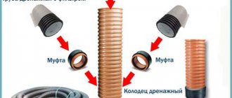
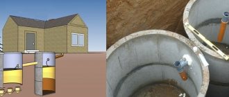
When installing sewerage in difficult areas: terrain with a large slope, connecting several pipelines located at different depths, etc., drop wells are used. The external sewage system of a private house is equipped with several types of wells, which not only help to monitor the performance of the system, but also, if necessary, carry out repairs.
The drop (overflow) well is one of the important elements. Such structures are installed on straight sections. Main purpose: reducing the speed of wastewater flow and changing the depth of the main line.
Purpose of drop wells
If there is a large difference in height between the sewer outlet from the house and the end point (cesspool, septic tank), the flow rate will be high. And this, in turn, threatens the formation of a blockage in the pipe, since the liquid will pass faster and heavy particles will settle on the surface of the pipe.
Purpose of these devices:
- decrease in flow rate;
- bypassing existing underground communications (gas, water, etc.);
- connection of outlets with different depths;
- aligning the level of sewage discharge with the level of discharge into the reservoir.
According to building codes, with a small drop of up to 0.5 m and a pipeline diameter of up to 600 mm, a manhole can perform the functions of a drop structure. There are several types of differential wells, which differ in design and functionality.
Purpose of the design
If there is a large difference in height between the starting and ending points of the sewer and drainage system, then a drop well is a mandatory intermediate element. The fact is that a large amount of water during movement creates a lot of pressure and load on the walls of the pipelines. As a result, this can lead to system destruction and failure.
The installation of a differential well is carried out in the following cases:
- If there is a need to forcibly reduce the speed of wastewater.
- The structure is installed when pipelines are laid over utility lines that were laid earlier.
- If the pipeline is laid under highways and other transport routes, the well used to transfer wastewater from a high pipe to a low one is an integral element of the sewer system.
In such cases, the rate of water flow naturally increases. To protect the system from the negative impact of such speed, it is necessary to install a differential well equipped with a water absorber.
Tip: If the pipeline has a diameter of 60 cm and a drop of 50 cm, then you can get by with a conventional inspection well.
Today, there are several types of differential wells, which have their own design and functional features. When choosing a container, you should pay attention to the characteristics of the soil, the topography of the site and the design of the pipeline.
Construction of a drop well
Domestic, storm and industrial sewer wells are similar in design. A standard well consists of the following elements:
- support bottom;
- working shaft;
- neck;
- cover and hatch.
The differential devices include a bumper or overflows, which are the main distinguishing feature. The difference in drainage can be both internal and external.
The need to use standard solutions
Drawing up a project for a drainage system requires calculating a large number of containers. They perform similar tasks and work under the same conditions. It takes a long time to design each well separately. Due to the large volume of work, errors or miscalculations are possible. In addition, it is necessary to ensure compliance with the requirements of SNiP and SP, which complicates the calculations. If a complex project is being drawn up with atypical operating conditions or network configuration, the calculation time will be too long.
To speed up design work, eliminate errors and miscalculations, an album “difference sewer well, standard project” has been compiled. This is a section of Standard Design Solutions, a catalog of available structures made from different materials. It is a collection of tables that display the parameters of containers of different sizes. They are designed so that you can easily select a design with the required number and diameter of pipes. The use of TPR significantly speeds up the process of drawing up working documentation, since the task of calculating each well separately is removed. You can choose ready-made solutions that meet regulatory requirements.
Among experts, a “standard storm drainage design” is considered a useful guide. Rainfall systems are complex and highly dependent on the terrain or structure configuration. At the same time, it is extremely difficult to calculate the amount of waste in advance. The specifics of the work also differ from domestic sewerage. Drainage comes from outside, collects on the roof or territory, and ends up in open trays. There is a constant need to transfer water to lower levels and enter it into underground collectors from the ground surface. The availability of ready-made catalogs compiled on the basis of current standards significantly speeds up design. Sometimes it is necessary to change the parameters of finished structures if operating conditions or other factors require it. Usually, a standard sewer drop well is used as a basis; a new look is obtained by making amendments to the dimensions or equipment of the container. At the same time, it is necessary to limit changes so that they do not affect existing rules and regulations. Any violation will result in refusal to approve the project.
Types of wells with drop
These structures are divided into four types:
- with inlet at the top and outlet at the bottom;
- a bumper in the form of a glass or pipe;
- with one vertical or angled damper;
- with a multi-stage fender system;
- chambers connected by a channel installed at an angle.
The first option is used only when the difference is no more than 3 m; in all other cases, options with bumpers are used. The latter option is used in places where it is necessary not to reduce the flow rate, but, on the contrary, to increase it.
Products of the POLIPLASTIC Group
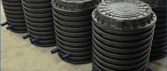
The structures sold by the company are made of plastic. Its advantages include low weight (ensuring low transportation costs and ease of installation of the structure), corrosion resistance, tightness, and long service life (up to 100 years). One of the product samples - a differential sewer well - has the following dimensions:
- diameter – 1600 mm;
- shaft height – 5750 mm;
- diameter of exits (inputs) – 1200 mm.
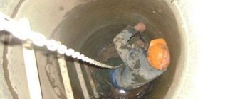
Inside there is a flow damper, which is required to reduce the speed of the medium. It also serves as an observation deck. The well is equipped with a ladder for ease of maintenance. Entrances and exits are made of polymer corrugated pipe.
It is possible to produce custom models according to Album No. 5 of the document “Chambers and wells of rainwater drainage. Standard materials for design 902-09-46.88.” Production is carried out according to designs that indicate the required height differences.
Material for drop wells
When constructing this type of sewer wells, the following is used:
- concrete;
- brick;
- fiberglass;
- polymer materials.
The easiest to install are finished products made of polymers or fiberglass, but they are also the most expensive. It is cheaper to use reinforced concrete rings or brickwork. However, to install the rings you will need to use special equipment, and to lay bricks you need to have such skills.
Classification of hydraulic structures
Types of wells are distinguished according to several characteristics:
- Type of network on which installation is carried out:
- domestic and industrial - access to wastewater discharged from residential buildings and industrial enterprises is provided;
- drainage – ensuring an audit of the site’s drainage network;
- storm drains - structures for draining into a system that drains rain and melt water.
- Construction material:
- reinforced concrete;
- polymers: polyethylene, polypropylene, polyvinyl chloride;
- brick.
- Functional purpose:
- examination rooms;
- distribution;
- accumulative;
- differential;
- absorbing.
Attention. The placement points, dimensions and requirements for installation of various types of wells are determined by SNiP 2.04.03-85.
Types of differential sewer wells
There are several types of differential wells, which is determined by different requirements for these devices.
Commonly used types include the following:
- Tubular differential wells with internal damper
. Such a device assumes the presence of a riser on the internal cavity of the structure. The riser is mounted to the inlet pipe, and due to it, the speed of passage of wastewater through the system is limited. - Water drop wells with internal damper
. In such structures, planes are installed that make it possible to dampen the speed of movement of wastewater. When water hits the plane, the rate of its movement decreases.
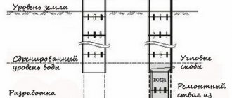
In addition, there is a modification of differential wells with a water seal. Structurally, such a well is a conventional design, but done exactly the opposite: the inlet channel of the pipeline is at the bottom, and the outlet channel is at the top, which allows you to increase the level of the system in the next section. Such wells are quite complex, so they are used infrequently, only when necessary. Conclusion
Overflow wells in sewers make it easier to operate the sewer system. When choosing a well, you should first consider plastic structures, since their advantages suggest that these devices are more convenient.
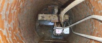
Installation of the structure
The construction of the most common concrete drop well includes the following stages of work:
- Preparatory activities : marking the territory, clearing debris and vegetation, arranging approaches, or better yet, an access road.
- Digging a pit for a mine . The depth is selected taking into account the parameters of the pipeline location and the need to form a cushion at the bottom.
- Filling with a cushion of sand and crushed stone (at least 15 cm thick), careful compaction, laying roofing felt waterproofing or filling with bitumen.
- Formation of the bottom part . The most rational option: laying a finished reinforced concrete slab. When pouring concrete, a reinforcing layer of steel rods with a diameter of 12-16 mm must be installed.
- Installation of concrete rings . The seams between the elements are sealed with concrete mortar. Bitumen waterproofing is applied to the outside of the walls.
- Installation of specific elements : riser with a receiving funnel, water trap. Construction of a bottom pit. A metal plate is placed at the bottom to protect the concrete from destruction by the jet.
- Installation of floor slab and hatch.
The water flow suppression system inside the well can be of 2 main types. Tubular dampers are made in the form of a riser from a pipe into which the sewage system is introduced. Second option: waterproof surface. A metal vertical or inclined plate is mounted in the well, onto which a stream of water is thrown. The profile of the entire well is selected taking into account the relief and volume of runoff. Drop wells are necessary for complex terrain of the site, because allow you to protect the sewer pipeline from rapid destruction. For their installation, it is better to use ready-made structures that you just need to dig in the right place and connect the pipeline. When making a well with your own hands, you should use standard designs, in particular a structure made of reinforced concrete rings.
Design features of wells
Installation of communications is accompanied by the installation of hydraulic structures made of various materials: brick, reinforced concrete, cast iron and plastic. Depending on the purpose, they are round and square, which are designed for large cross-section highways. The diameter of the structure depends on the size of the pipeline:
- for a main with a cross-section of up to 30 cm - a well of at least 70 cm;
- up to 60 cm – 100 cm;
- up to 100 cm – 150 cm.
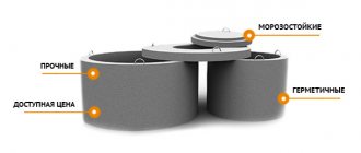
Concrete wells
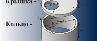
Due to their strength, speed of installation and standard sizes, wells made of reinforced concrete rings are very popular. Their components are:
- wall ring;
- cover with hatch;
- bottom.
To create a sealed structure, the rings are treated with waterproofing mastic. The elements are connected to each other with cement-sand mortar. Universal products are suitable for installing any type of well.
Components of a concrete structure
Attention. Well shafts are equipped with brackets or ladders for descent.
Polymer wells
Plastic structures are inferior in popularity to concrete structures, but they are often used when installing private communications for drainage of waste and storm water. Plastic wells are assembled from several parts:
- Luke;
- neck or telescopic extension;
- mine;
- sealing cuffs;
- tray part.
Plastic well
Among the advantages of plastic: tightness, lightness, lack of corrosion. But with all strength indicators, there is a risk of tank deformation.
Advice. The performance characteristics and service life of brick wells are inferior to structures made from other materials, so they are built very rarely.
Water intake wells
Water collected by storm sewers is discharged into storage wells. It can be cleaned and used for irrigation or technical needs, pumped out, discharged into the nearest ravine, reservoir, etc. The capacity of the drainage well is determined by the catchment area, the amount of precipitation, and the intensity of snow melting. It should be such that the mine does not overflow even during periods of peak loads.
- the main part is a shaft made of large-diameter corrugated plastic pipe, concrete rings, with brick walls, etc. Installed vertically at the lowest point of the linear drainage system;
- the bottom should not allow water to pass through; for prefabricated structures, during its installation, waterproofing of joints and connections is carried out;
- branch pipes are installed at the entry points of sewer pipes, and they are waterproofed. They are placed in such a way as to avoid the reverse flow of water into the linear drainage system when filling the water intake tank;
- the cover is removable, covers the above-ground part of the shaft, and is used to access the inside of it, control the condition of the well, and pump out water.
To prevent the water intake well from silting up, sand traps and siphons are used when installing storm sewers, and it is possible to install filtration equipment. Siltation can occur due to cracks, gaps in the walls, at the joints of concrete rings, and pipe entries. During installation, these areas are isolated and treated with sealant. Installation is carried out on a base filled with crushed stone and sand or using concreting. A foundation pit is first prepared for the mine. After the walls are leveled vertically, the pit is backfilled with constant compaction to maintain the verticality of the shaft.
Depending on the height of the drop and the diameter of the connected pipeline, wells with different types of internal structure are used.