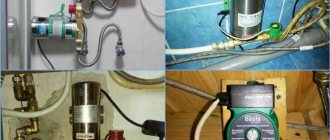
When supplying a building with water from a well or well, a hydraulic accumulator must be installed, which is a container of suitable volume. It is usually used in conjunction with a special pressure switch. For the hydraulic accumulator, it is a control device that allows you to reduce the number of pump operating cycles.
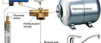
Main components of a pumping unit with a hydraulic accumulator
Hydraulic tank functions
In the process of organizing an autonomous supply of water from shallow wells in private homes, a pumping station is most often used to lift it to the surface. It is a unit assembled from a self-priming pump, a storage tank and instruments through which the station is put into operation and pressure is controlled.
- However, the station can only be installed superficially and can extract water from a maximum depth of 8 meters (we do not take ejector units into account). In deep water intakes, a submersible pump is used, and the hydraulic accumulator for it must be selected individually.
- There may be more than one such container in the system if, for example, higher pressure needs to be ensured on the upper floor. There are situations when the station simply cannot become a replacement for a hydraulic storage tank, especially since not only cold water supply is organized in the house, but also hot water.
A diagram in which, in addition to the pumping station, there are two more hydraulic tanks Source kadetbrand.ru
- The pressure in a hydraulic accumulator integrated into a particular system will not be the same, just as the containers themselves should be different. They may be similar in appearance, have the same volume or shape, and sometimes even color (it all depends on the manufacturer), but if you place the device on a network not intended for it, this will quickly make itself felt.
Only a tank for cold water is called a hydraulic accumulator; in a hot water system it is already an expansion tank. You can still put it on heating, but not on cold water. What's the difference?
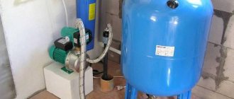
Distinctive features
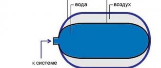
Inside any hydraulic tank there is a rubber bulb (membrane). So, in tanks for cold water supply systems, the water is inside this bulb, and the air pumped inside occupies the space between it and the walls of the tank itself, as shown in the photo:
Pressure in the hydraulic accumulator of the pumping station and its internal structure Source nasosovnet.ru
- In an expansion tank, the opposite is true: air is pumped into a rubber balloon, and water is around it, in contact with the metal body. Since it is intended for hot water, the permissible pressure and temperature range will be approximately the following: 10 bar/+70 degrees.
- A tank with such indicators is universal; it can also be used with cold water. If the container is intended only for cold water, the permissible pressure will be significantly lower. You can navigate the characteristics by looking at the information label pasted by the manufacturer on the container body.
The permissible air pressure is indicated on the information plate Source sima-land.ru
- And one more important question that requires clarification to understand the topic. The tank body has a certain capacity, which is specified by the manufacturer. Many people mistakenly believe that this is the amount of water that is placed inside. However, this is not so, because part of the container, and a large part, is occupied by air. The tank can only be filled to a third with water (for a body volume of 100 liters, about 30 liters of water).
Note! More water can fit into the tank only when the pressure in the accumulator - 50 liters, or any other volume - is zero. That is, there is no air in it - and, accordingly, the device is inoperative.
On what basis is pressure set?
So, we have already understood that hydraulic tanks differ only in their purpose - for a cold network or a hot one. The volume of the housing does not matter during the settings, so the pressure in a 24-liter accumulator will be the same as in the case of a hundred-liter tank.
- More volume (the shape of the body does not matter at all) means more air. Accordingly, more water will fit. The manufacturer still maintains the balance, and the pressure in the air cavity will be the same in any container (standard is 1.5 bar).
Volume and shape do not matter Source pumpekhoob.com
- When the pump is off, the operating pressure in the network should be twice as high as when it is on. However, under no circumstances should it exceed the limit stated for this device by the manufacturer.
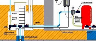
- If necessary, the factory settings can be changed - exactly how depends on the structure of the system. If this is a pipeline that supplies water from a well to the house, the accumulator is usually configured in accordance with the factory parameters of the pressure sensor installed on it.
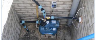
A well pump connected to a hydraulic accumulator Source de.decorexpro.com
- Most often the range varies between 1.4 and 2.8 bar. The pressure in a 100 liter cold water accumulator (or any other tank by volume) is adjusted 0.2 bar lower (both indicators). This makes it possible to avoid unnecessary pressure surges when turning on taps or plumbing fixtures that use water.
- If another tank is installed in the system - for hot water, then its settings are no longer oriented towards its relay, but towards the cold water accumulator, with a decrease of the same 0.2 bar.
- Maintaining such a gap is an important point, because with higher pressure in the hot pipeline, the float on the automatic air vent will constantly shift and let air in, which should not be allowed.
Advice! To obtain precisely specified pressure parameters, the air already in the tank should be completely vented, and only then pumped up to the required limit.
Pressure sensor with pressure gauge on the hydraulic tank Source rmnt.mirtesen.ru
See also: Catalog of house projects with a boiler room
In a system in which a hydraulic accumulator is present, a drop in pressure usually indicates either a loss of air through the inlet valve or a breakthrough of the rubber membrane. At the same time, when water begins to be consumed, the relay begins to make constant clicks, and the pump constantly turns on.
On a note! In a hot water supply, when the pressure drops, the emergency valve begins to leak.
Having discovered such problems, it is necessary to find out what pressure should be in the pumping station in the accumulator and compare it with the actual one. Perhaps you just need to pump up the air. If this does not help, you will have to disassemble the housing and check the integrity of the membrane.
Reviews
Among budget relays, the most reliable are devices from the Italian concern ItalTecnica (model RM-5). True, they are rather complicated to connect and are designed only for low-power electric motors.
Relays from the Condor company (Germany), namely models MDR 5-5 and MDR 5-8, have proven themselves well (in the middle price segment). These devices can be connected to single-phase and 3-phase networks. They can be installed on a hydraulic accumulator, which turned out to be, as many users testify, very convenient.
Among the elite class models, the most popular were relays from the Danish brand Grundfos (models FF 4-4 and FF 4-8). However, it should be taken into account that these devices cannot be connected to the network, since they are designed for low currents. That is, to turn on the pump you will need a magnetic starter.
In the absence of a central water supply, owners of country houses install pumping stations. But, like any technical device, the pumping station can fail. Repairing a pumping station with your own hands: common problems and their solutions, read carefully.
Read about how to connect a hydraulic accumulator to a well in this section.
How to set the pressure on the relay
Questions like: “What pressure should be in a 100-liter hydraulic accumulator?” are asked by readers with enviable consistency. We have already established that the volume of the tank does not affect these parameters, so 50 liters or 24 - there is no difference. It is important to install a sensor that stabilizes the operation of the system and correctly set the upper and lower pressure limits on it.
The pressure will be controlled by a relay Source stroje.bazar.sk
So let's figure out how to set up the accumulator pressure switch. The process depends on the type of device, which can be either mechanical or electronic. In the mechanical one, which is shown in the photo above, the closure of contacts in the power circuit is provoked by compression of the spring. The electronic device is controlled by a pressure sensor, which changes the electrical resistance by compressing the piezocrystal.
Electronic pressure switch for hydraulic accumulator Source fervently.ru
Despite the fact that the network pressure control sensor may be located quite far from the pump relay, it still protects the water supply from leaks and destruction. In an electronic device, all settings are made by pressing buttons on the front panel, but in a mechanical device you have to tighten the nuts.
Some very important nuances depend on how to adjust the water pressure switch with a hydraulic accumulator. With this you can achieve:
- increasing the capacity of the tank, which increases with increasing pressure;
- extending the service life of the tank membrane by reducing the upper pressure value;
- stabilizing the water pressure in taps and other points of analysis by reducing the difference between the upper and lower pressure indicators on the relay, as shown in the picture below.
How to reduce pressure difference Source greendom74.ru
Preventive actions
If the system is malfunctioning and the pressure gauge readings confirm this, the following preventive measures are taken:
- Parts sensitive to mechanical stress are checked and, if necessary, adjusted.
- It is recommended to clean the contacts.
- If the relay does not operate, do not rush to disassemble it; it is better to knock on the body with a light object. Experts note that such manipulation often helps.
- Once a year, lubricate the moving parts of the device with grease.
- If you tighten and tighten the adjustment nuts, the relay will not work at all. This is a common mistake.
The installation price fluctuates over a wide range; the minimum cost in all regions of Russia does not exceed 1000 rubles. Electronic modifications are more expensive because they show more accurate data.
Video description
An example of setting up a pressure switch in the video:
See also: Catalog of companies that specialize in swimming pools and related equipment
Step by Step Actions
We offer instructions in pictures that will help you understand how to set up a mechanical relay:
| No. | Photo for clarity | A comment |
| 1. | Note: Relay settings must be done with the system fully assembled and put into operation. | |
| 2. | Having previously de-energized the device and unscrewed just one screw with a screwdriver, you need to remove the relay cover. | |
| 3. | The large spring, by changing the pump activation pressure, is responsible for shifting the entire operating range. A small spring, by changing the shutdown pressure, changes the operating range up or down. | |
| 4. | The factory setting of such a relay most often corresponds to 1.4/2.8 atm. Let's say you need to shift the range upward by setting it to 2/3 atm. To adjust the activation pressure, you need to tighten the nut on the large spring a couple of turns clockwise. Use a socket or open-end wrench. | |
| 5. | Before carrying out this procedure, you need to relieve the pressure in the system by unscrewing any tap and waiting for the pump to turn on. If at this moment the pressure gauge shows 2 atmospheres, then everything worked out for you. | |
| 6. | If the number on the pressure gauge display is less than necessary, you will have to tighten the nut of the large spring a little more. With a higher value, the nuts need to be loosened slightly. After each displacement of the nut, the entire procedure with releasing pressure must be repeated. | |
| 7. | The cut-in pressure is set. Now our task is to reduce the difference between it and the upper limit, since in the factory setting of the device it was 1.5 atm, but we need to make it 1 atm. To achieve this, you need to loosen the nut on the small spring. Start with one full turn. | |
| 8. | To make sure the settings are correct, perform the same manipulation of opening the tap. Only now the pressure gauge readings need to be taken not at the moment the pump is turned on, but at the moment it is turned off after the tap is closed. According to the parameter given as an example, the arrow should show 3 atmospheres. Having achieved the required pressure gauge readings, replace the relay cover and you can connect the pump to the network. |
Photo source: Youtube.com
Installation
Often the HA kit is sold disassembled, and the control unit must be installed yourself.
Connecting the pressure switch to the hydraulic accumulator looks like this in stages:
- The station is disconnected from the network. If water has already been pumped into the storage tank, it is drained.
- The device is fixed permanently. It is screwed onto the 5-pin fitting of the unit or onto the outlet pipe and must be firmly fixed.
- The wiring diagram is normal: there are contacts for the network, pump, and grounding. The cables are passed through holes on the housing and connected to contact blocks with terminals.
Electrical connection to the pump
Video description
What the pressure should be, see the video:
Optimizing underpressure
The problem of excess pressure also occurs, but quite rarely. Most often it is not enough, and this issue is solved in several ways. Here are the two most popular.
With booster pump
A booster pump is included in the system. That is, this pump is not present to supply water, but to forcibly increase its pressure. This solution can be considered optimal when there is water in the source, but due to its distance from the distribution points, it loses pressure along the way.
Scheme with booster pumps Source ppt-online.org
It is ideal when such a pump is controlled automatically, which itself starts and stops its operation when necessary. This option is suitable for both private houses and apartments, but in the latter case there is a risk of leaving neighbors without water.
Using a storage tank
If there is not enough water in the well (the flow rate of the source is reduced), installing a booster pump will not only not solve the problem, but will also aggravate it. In this case, a sufficiently large storage tank must be installed in front of this pump, and in the absence of water intake, water will be pumped into it.
In this case, the owner himself will decide what pressure is in the accumulator, because this is not important. If such a tank is equipped with a float sensor, it will itself give the pump a command to turn on when the water in the tank is used up to a certain limit.
System with large storage capacity Source seid-nn.ru
If you place the container in the attic, it will also be filled by means of a pump, but it will flow to the flow points by gravity. True, the pressure will not be strong enough, and most likely, you will have to install another pump that will supply water from the tank. By using the second pump, you can place the barrel anywhere – even in the basement.
Design and principle of operation
The device looks like a box of various shapes with controls under the lid. It is attached to one of the outlets of the fitting (tee) of the container. The mechanism is equipped with small springs that are adjusted by turning the nuts.
Operating principle in order:
- The springs are connected to a membrane that responds to pressure surges. An increase in indicators compresses the spiral, a decrease leads to stretching.
- The contact group reacts to these actions by closing or opening the contacts, thereby transmitting a signal to the pump. The connection diagram necessarily takes into account the connections of its electrical cable to the device.
- The storage space fills up and the pressure increases. The spring transmits the pressure force, the device operates according to the set values and turns off the pump, sending it a command to do so.
- The liquid is consumed - the pressure weakens. This is fixed, the engine turns on.
The assembly consists of the following parts: a housing (plastic or metal), a membrane with a cover, a brass piston, threaded pins, metal plates, cable sleeves, terminal blocks, a hinged platform, sensitive springs, and a contact assembly.
The operating algorithm of the control device is as simple as possible. The mechanism responds to changes in the number of atmospheres inside the drive. The moving platform is raised or lowered by springs depending on the pressure on the piston, which in turn interacts with contacts that signal the pump to start or stop pumping.
Causes of hardware problems
Statistics of malfunctions in the operation of household pumping stations indicate that most often problems arise due to a violation of the integrity of the accumulator membrane, pipeline, water or air leakage, as well as due to various contaminants in the system.
The need to intervene in its work may arise for many reasons:
- Sand and various substances dissolved in water can cause corrosion, lead to malfunctions and reduce equipment performance. To prevent clogging of the device, it is necessary to use filters that purify the water.
- A decrease in air pressure in the station causes frequent operation of the pump and its premature wear. It is recommended to measure the air pressure from time to time and adjust it if necessary.
- The lack of tightness of the joints of the suction pipeline is the reason that the engine runs without turning off, but cannot pump liquid.
- Incorrect adjustment of the pressure of the pumping station can also cause inconvenience and even breakdowns in the system.
To extend the life of the station, it is recommended to carry out periodic inspections. Any adjustment work must begin by disconnecting from the power supply and draining the water.
Energy consumption and maximum pressure should be checked periodically. An increase in energy consumption indicates friction in the pump. If the pressure drops without any leaks detected in the system, then the equipment is worn out
Types of hydraulic accumulators
Hydraulic accumulators are used in heating systems, cold and hot water supply.
The containers differ in size, purpose, and design. The design and functions of the tanks remain unchanged.
By purpose:
- for hot water (red);
- for cold water (blue).
Price
Price
The difference between storage tanks is the material from which the membrane is made. The container intended for drinking (cold) water uses rubber that is safe for human health.
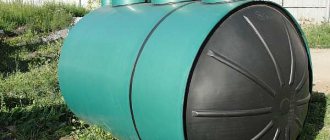
By execution:
- vertical models - used for limited space;
- The horizontal version is used in conjunction with an external pump mounted on the housing.
Cost of vertical hydraulic accumulators
Cost of horizontal hydraulic accumulators
Each type of device is equipped with a special device for bleeding air. A valve is installed at the top of the vertical hydraulic tanks. The accumulated air is released through it, preventing the formation of plugs in the system. Horizontal tanks have an assembly of pipes and ball valves. Discharge is carried out into the sewer. In tanks with a volume of less than 100 liters, valves and drain units are not installed. Air is removed during preventative maintenance.
The storage devices are installed in heated rooms. The devices must be provided with free access for repair and maintenance.
Verification methods
To check the pressure, you can use a car pressure gauge
. The air pumped into the container at the factory gradually escapes through the rubber membrane and nipple. Rarefaction of the gas cavity leads to excessive stretching of the rubber bulb when filling it with liquid. Without resistance, the membrane wears out quickly and may burst. Air pressure is measured with a pressure gauge. The best option is a car measuring device.
The manufacturer's instructions indicate the number of checks for the device model. The average is 2 times a year. Before starting the parameter measurement procedure, all liquid must be drained from the tank. The pump is disconnected from the power supply system. The tank must be empty at the time of measurements. Control is required before connecting the device to the system. During storage in a warehouse, some air may leak out of the tank. The operating pressure is indicated in the product data sheet.
To check, unscrew the decorative cap covering the nipple. The node is located in the upper part of the housing. A pressure gauge is connected to the spool. The device must have a minimum error. Electronic and automotive devices are recommended. It is better not to use cheap plastic pressure gauges; they have a significant error in their readings. If the level is below the factory parameters, air is pumped in using a compressor. The hydraulic accumulator is left for a day for monitoring. After the next measurement that meets the standard, the device is installed. Exceeding the optimal pressure is eliminated by bleeding the air.
The number of checks depends on how long the plumbing system has been in use. For summer cottages where communications are operated in the spring and summer, indicators are monitored before the start of the season. A sign of a decrease in air pressure is the frequent turning on and off of the pump. In case of any deviations from the norm, an unscheduled inspection is carried out. Minor air loss can be pumped up with a car pump.
Preventing problems
The main problems include:
- reducing the pressure inside the accumulator;
- water not entering the hydraulic tank.
| Problem | Cause of occurrence |
| Pressure drop | The appearance of leaks at the flange-nipple interface. The occurrence of leakage at the junction of the flange and the pear-shaped membrane. |
| No water ingress | Clogged filters. A sharp decrease in power supply or frequent power outages. Air entering the hydraulic tank. |
To prevent problems, regular preventive measures are required, namely:
- examination of the inside of the tank every 6 months;
- annual check of membrane tightness;
- monthly inspection of the pump for external defects;
- Check the pressure switch every six months.
If the use of the hydraulic accumulator is stopped for the winter, then it is necessary to drain the water from it, and before use, check all elements for external and internal damage.