The technology of any construction involves sequential work. In this case, control is carried out:
- Input - the quality of construction materials and working documents is checked;
- Operational - the correctness of the work is checked); acceptance (correctness and quality of completed work.
To check the quality of work on the construction of water supply and sewerage facilities, their systems are tested. For example, testing internal sewerage and drainage systems. The procedure, type and technology of testing (testing, examination) are justified by many years of experience and are prescribed by law in regulations.
Work acceptance procedure
When accepting such work, the tests themselves are carried out first, which can be:
- Hydraulic - only non-pressure drainage systems are exposed to them, be it wastewater pipelines or storm sewers. testing is carried out in areas between wells by filling the system with process water. The tests are carried out in two stages - checking pipes and connections before filling the soil and checking the performance of the entire sewer system after filling the soil. Tests are carried out by pumping water into wells or receiving grids for 30 minutes; during the tests, the performance of the system is measured and the tightness of seams and joints is monitored. Tests may also be performed to determine the ability of pipes and connections to withstand the maximum allowable pressure throughout the entire drain.
- Pneumatic - during such tests, the ability of the waste system to withstand the design pressure is checked, according to GOST standards or design documentation. For such a series of studies, specialized organizations with the necessary equipment and licenses are involved; the process itself includes checking the pressure in the system or in its individual sections when supplying air under pressure.
If during the experiments the entire system met the standard indicators of SNIP 3.05.04-85, then an acceptance certificate for the work performed is drawn up, otherwise a defective statement and a drainage troubleshooting report are drawn up.
During periodic monitoring at enterprises with drinking water pipelines, external drainage systems are also tested during disinfection or treatment with special reagents.
Preliminary tests
During a preliminary leak test, the pipeline, which is not sprinkled, is checked within 30 minutes. Pressure in the system is created and maintained by filling the riser or higher well with water, without allowing the water level to drop by more than 20 cm.
When testing free-flow pipelines, the value of hydrostatic pressure is taken from the working documentation. For concrete and ceramic pipes, this is 0.04 MPa (0.4 kgf/cm²), for polymers there are no standards. If there are no visible leaks, the system is considered to have passed the test.
Testing basic principles
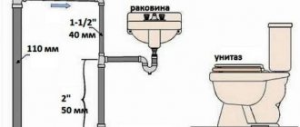
The internal system includes the following objects:
- All plumbing points and household appliances that drain water;
- The entire pipeline connected to the central manifold;
- Central sewer riser.
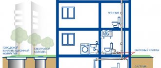
The external test system includes:
- A pipeline placed outside a building to transport wastewater to a point of accumulation or disposal;
- All inspection and rotary wells;
- Storm drainage channels.
In order for the testing to pass efficiently and fully reflect the condition and performance of the sewer communication, it is necessary to adhere to the basic rules:
Thus, all plumbing points must be cleared of possible construction and natural debris before carrying out work; It is worth checking all points for cracks, chips and other damage; It is important to monitor the evenness of all straight sections of the network. There should be no deflections or bends; All vertical risers must be checked using a plumb line; To check the pipeline, you can use either a hydraulic method (spill method) or a pneumatic method (pumping the system with air); Important: drainage of sewer lines can only be carried out if the air temperature around does not fall below +5 degrees
If the outside temperature is below the specified parameter, then a pneumatic testing method is used. It is worth conducting a separate communication check for each floor of the building. To do this, audit plugs are installed on all other floors.
After completing the installation work of internal sewerage systems and drains, the installation organization must carry out their tests and draw up a report in accordance with Appendix “D” “Internal sanitary systems of the building” (updated edition of SNiP 3.05.01-85). These tests must be carried out by pouring water by simultaneously opening 75% of the sanitary fixtures connected to the area being tested. The test method gives rise to the “everyday” name of the act – sewer spill act or sewer spill act. However, the name of the act, according to the regulatory documentation, is as follows: an act of testing internal sewerage and drainage systems
.
We have figured out the correct name of the act and its purpose. Now let’s take a closer look at the form of the test report for internal sewerage and drainage systems and the method of filling it.
First, fill in the name of the system on which the tests were carried out. We take the name of the system from the design documentation. For example, this could be “domestic sewerage K1”.
Next, you need to fill in the name of the capital construction project. There is nothing complicated here. We take information about the name from the design documentation or construction permit. After this, we enter information about the city in which the capital construction project is located and the date of the tests.
The block in which data about the commission that conducted the tests is entered includes the following information: the name of the customer’s organizations, the general contractor, the installation (construction) organization, as well as the positions, initials and surnames of representatives of these organizations.
In paragraph 1 of the test report for internal sewerage and drainage systems, data (name) is entered on the design organization, design documentation code, drawing numbers in accordance with which installation work was performed.
In paragraph 2 we indicate the number of simultaneously open sanitary fixtures and the time during which the tests were carried out. Sanitary fixtures include bathtubs, washbasins, shower trays, drains, bidets, toilets, closet bowls, urinals, sinks, sinks, and drains. During tests in accordance with the rules, at least 75% of the sanitary fixtures connected to the tested area must be open simultaneously.
Clause 3 of the sewerage testing report includes data on defects identified during testing. If no defects are found, then we make a note that during inspection during testing, no leaks were found through the walls of the pipelines and joints.
Based on the results of the tests, a decision is made by the commission, which is recorded in the end of the act. As a rule, this is a template paragraph, which is only supplemented with data about the name of the tested system.
After completion of the tests, the act of spilling is signed by all members of the commission. Changing the form of the act or deviating from it is not allowed.
The quality of installed sewage systems in a country house and beyond is checked at all levels. First of all, all building codes and requirements must be observed. Then the installation is supervised. And at the end, tests are carried out and a sewerage spill report is drawn up, a sample of which can be found on the Internet.
TANK STRUCTURES
7.31. Hydraulic testing for water tightness (tightness) of capacitive structures must be carried out after the concrete has reached its design strength, after they have been cleaned and washed.
Waterproofing and filling of tank structures with soil should be carried out after obtaining satisfactory results of hydraulic testing of these structures, unless other requirements are justified by the design.
7.32. Before conducting a hydraulic test, the tank structure should be filled with water in two stages:
first – filling to a height of 1 m with exposure for 24 hours;
the second is filling to the design level.
A tank structure filled with water to the design level should be kept for at least three days.
7.33. A tank structure is recognized as having passed the hydraulic test if the loss of water in it per day does not exceed 3 liters per 1 m2 of the wetted surface of the walls and bottom, no signs of leakage are found in the seams and walls and no soil moisture is detected at the base. Only darkening and slight sweating of individual places is allowed.
When testing the water resistance of tank structures, the loss of water due to evaporation from the open water surface must be taken into account additionally.
7.34. If there are jet leaks and water leaks on the walls or soil moisture at the base, the capacitive structure is considered to have failed the test, even if the water loss in it does not exceed the norm. In this case, after measuring the water loss from the structure when it is completely flooded, the areas to be repaired must be recorded.
After eliminating the identified defects, the tank structure must be retested.
7.35. When testing tanks and containers for storing aggressive liquids, water leakage is not allowed. The test should be carried out before applying the anti-corrosion coating.
7.36. Pressure channels of filters and contact clarifiers (prefabricated and monolithic reinforced concrete) are subjected to hydraulic testing with the design pressure specified in the working documentation.
7.37. The pressure channels of filters and contact clarifiers are recognized as having passed the hydraulic test if, upon visual inspection, no water leaks are detected in the side walls of the filters and above the channel and if within 10 minutes the test pressure does not decrease by more than 0.002 MPa (0.02 kgf/cm2) .
7.38. The drainage tank of cooling towers must be waterproof, and during hydraulic testing of this tank on the inner surface of its walls, darkening or slight sweating of individual places is not allowed.
7.39. Drinking water reservoirs, settling tanks and other capacitive structures after the installation of floors are subject to hydraulic testing for water tightness in accordance with the requirements of paragraphs. 7.31-7.34.
The drinking water reservoir, before waterproofing and backfilling with soil, is subject to additional testing for vacuum and excess pressure, respectively, with vacuum and excess air pressure in the amount of 0.0008 MPa (80 mm water column) for 30 minutes and is recognized as having passed the test if the values are accordingly vacuum and excess pressure in 30 minutes will not decrease by more than 0.0002 MPa (20 mm water column), unless other requirements are justified by the design.
7.40. The digester (cylindrical part) should be subjected to hydraulic testing in accordance with the requirements of paragraphs. 7.31-7.34, and the ceiling, metal gas cap (gas collector) should be tested for tightness (gas tightness) pneumatically to a pressure of 0.005 MPa (500 mm water column).
The digester is maintained under test pressure for at least 24 hours. If defective areas are detected, they must be eliminated, after which the structure must be tested for pressure drop for an additional 8 hours. The digester is recognized as having passed the leak test if the pressure in it does not decrease within 8 hours more than 0.001 MPa (100 mm water column).
7.41. The caps of the drainage and distribution system of filters, after their installation, before loading the filters, should be tested by supplying water with an intensity of 5-8 l/(s×m2) and air with an intensity of 20 l/(s×m2) with three repetitions of 8-10 minutes. Defective caps discovered in this case must be replaced.
7.42. Before being put into operation, completed pipelines and household and drinking water supply structures are subject to rinsing (cleaning) and disinfection by chlorination, followed by rinsing until satisfactory control physical, chemical and bacteriological analyzes of water are obtained that meet the requirements of GOST 2874-82 and the “Instructions for monitoring the disinfection of household – drinking water and disinfection of water supply facilities with chlorine during centralized and local water supply” of the USSR Ministry of Health.
7.43. Washing and disinfection of pipelines and drinking water supply structures must be carried out by the construction and installation organization that carried out the laying and installation of these pipelines and structures, with the participation of representatives of the customer and the operating organization with control carried out by representatives of the sanitary and epidemiological service. The procedure for washing and disinfecting pipelines and domestic water supply structures is set out in recommended Appendix 5.
7.44. A report must be drawn up on the results of the washing and disinfection of pipelines and domestic and drinking water supply structures in the form given in mandatory Appendix 6.
The test results of capacitive structures should be documented in an act signed by representatives of the construction and installation organization, the customer and the operating organization.
Persons - members of the commission
In a separate paragraph in the inspection report for external or internal sewerage, it is necessary to record all the data about the members of the commission. These are:
- Representatives from the customer organization.
- Representatives from the general contractor. These persons are responsible for the correct installation of drains in case they do not comply with technical and operational standards during a spill.
- Members of the design organization who were involved in the development of the communication project being tested.
- A representative of a company or organization that was engaged in soil research at the site for the installation of external or internal communications. This office bears full responsibility for the inconsistency of the data received on the site regarding environmental and climatic conditions for the construction of sewer communications.
Thus, in the paragraph of the test acceptance certificate, it is necessary to include all the initials and surnames of the commission members with their signatures.
Parties involved in the review
If we are talking about more or less large-scale construction, where several organizations are involved, not counting the customer, tests of sewer systems are carried out by all of them, after which the results are documented in the appropriate inspection report.
Typically, inspection of the sewerage system involves:
- the organization that compiled the project and is responsible for the correctness of calculations and selection of materials and components;
- a company that analyzed climatic and soil conditions and made recommendations for the design of the external components of the sewer system;
- a contractor who was directly involved in installation work related to the laying of internal and external sewer networks and is responsible for compliance of the activities carried out with the project and existing requirements specified in SNiP;
- a customer who controls the correct testing of discharge pipes, connections and some functional units of the sewer network inside the building and in the external section of the wastewater disposal system.
Each of the representatives of the parties participating in the tests and signing the final inspection report is responsible for inaccuracies and shortcomings that arose during testing of sections of the system, individual nodes or the entire network as a whole.
How to test a finished sewerage system
The test method gives rise to the “everyday” name of the act – sewer spill act or sewer spill act. However, the name of the act, according to the regulatory documentation, is the following: act of testing internal sewerage and drainage systems.
Info
We have figured out the correct name of the act and its purpose. Now let’s take a closer look at the form of the test report for internal sewerage and drainage systems and the method of filling it
Attention
Next, you need to fill in the name of the capital construction project. There's nothing complicated here
We take information about the name from the design documentation or construction permit.
Testing of external sewerage networks
Preliminary tests Acceptance tests Pneumatic tests Preliminary tests Hydrostatic pressure in the pipeline during its preliminary testing must be created by filling the riser installed at its upper point with water, or by filling the upper well with water, if the latter is to be tested. In this case, the value of hydrostatic pressure at the top point of the pipeline is determined by the amount of excess of the water level in the riser or well above the pipeline shelyga or above the groundwater horizon, if the latter is located above the shelyga. The magnitude of hydrostatic pressure in the pipeline during testing must be indicated in the working documentation. For pipelines laid from free-flow concrete, reinforced concrete and ceramic pipes, this value, as a rule, should be equal to 0.04 MPa (0.4 kgf/cm2).
Testing of external network Testing of external sewerage is carried out mainly by hydraulic method. Work performed:
- pipeline slope control;
- the pipeline is tested for leaks;
- examination of wells and other equipment.
The slope level of the external sewer is checked by level.
The test is carried out between wells, in stages, each section is disconnected from the system using a plug. Test scheme for non-pressure systems::
- checking pipes for blockages and debris from construction, and flushing if necessary;
- spill test - a section of the system is filled with water; if no leaks are detected within 10 minutes, the test is passed.
Water is supplied to the pressure sewer under pressure. If the pressure at the inlet and outlet of the pipe is the same, the test is also considered passed.
The check includes:
- testing the pipeline for leaks (carried out as described above. For testing, sections of pipes located between wells or other elements of the system are taken);
- checking the pipeline slope level;
- testing of wells and other equipment;
- checking the performance of storm drains.
A level is used to check the level of pipe laying required for a gravity sewer system.
If a pressure sewer test is being carried out, then water must be supplied to the pipeline system at the pressure specified in the design documents. The test of pressure sewerage pipelines is considered successful if the pressure value in the flow into the network and at the exit from it is the same.
SP 40-102-2000: Testing and commissioning of pipelines
Introduction Scope of application General provisions Design of internal water supply networks Design of internal sewerage and watercourses Design of external water supply Design of external sewerage, gutters and drainages Installation of pipelines
8.1 According to SNiP 3.05.04, pressure and non-pressure water supply and sewerage pipelines are tested for strength and density (tightness) by hydraulic or pneumatic methods twice (preliminary and final).
8.2 Preliminary test (excessive) hydraulic pressure during strength testing, performed before backfilling the trench and installing fittings (hydrants, safety valves, plungers), must be equal to the design operating pressure multiplied by a factor of 1.5.
8.3 The final test hydraulic pressure for density tests performed after backfilling the trench and completion of all work on this section of the pipeline, but before installing hydrants, safety valves and plungers, in place of which plugs are installed during the test, must be equal to the design working pressure multiplied by coefficient 1.3.
8.4 Before testing pressure pipelines with socket connections with O-rings, temporary or permanent stops must be installed at the ends of the pipeline and at the bends.
8.5 Preliminary hydraulic testing of pressure pipelines should be carried out in the following order:
— fill the pipeline with water and keep it without pressure for 2 hours;
— create test pressure in the pipeline and maintain it for 0.5 hours;
— reduce the test pressure to the design pressure and inspect the pipeline.
The pipeline is kept under operating pressure for at least 0.5 hours. Due to deformation of the pipeline shell, it is necessary to maintain test or operating pressure in the pipeline by pumping water until complete stabilization.
The pipeline is considered to have passed the preliminary hydraulic test if no ruptures of pipes or joints and connecting parts are detected under test pressure, and no visible water leaks are detected under operating pressure.
8.6 The final hydraulic test for density is carried out in the following order:
— a pressure should be created in the pipeline equal to the design operating pressure and maintained for 2 hours; when the pressure drops by 0.02 MPa, water is pumped;
— the pressure is raised to the test level for a period of no more than 10 minutes and maintained for 2 hours.
The pipeline is considered to have passed the final hydraulic test if the actual leakage of water from the pipeline at the test pressure does not exceed the values specified in Table 5.
8.7 Hydraulic testing of gravity sewer networks is carried out after completion of waterproofing work in wells in two stages: without wells (preliminary) and together with wells (final).
8.8 The final test of the sewerage pipeline together with the wells is carried out in accordance with SNiP 3.05.04.
8.9 Hydraulic tests of systems made of polymeric materials of internal pipelines are carried out at positive ambient temperatures no earlier than 24 hours after the last welded and adhesive joint is made.
8.10 Hydraulic testing of internal drainage systems is carried out by filling them with water to the full height of the risers. Tests are carried out after external inspection of pipelines and elimination of visible defects. Hydraulic testing of glued pipelines begins no earlier than 24 hours after the last connection. The drainage system is considered to have passed the test if, 20 minutes after its filling, an external inspection of the pipelines reveals no leaks or other defects and the water level in the risers has not decreased.
8.11 Pneumatic tests of pipelines made of polymer materials are carried out during ground and above-ground installation in the following cases: ambient air temperature below 0 °C; the use of water is unacceptable for technical reasons; There is no water in the quantity required for testing.
The procedure for pneumatic testing of pipelines made of polymeric materials and safety requirements during testing are established by the project.
8.12 Preliminary and final tests of gravity sewer networks made of large-diameter pipes may be carried out pneumatically. Preliminary tests are carried out before the final filling of the trench (welded joints are not covered with soil). A test pressure of compressed air equal to 0.05 MPa is maintained in the pipeline for 15 minutes. At the same time, welded, glued and other joints are inspected and leaks are detected by the sound of leaking air, by bubbles formed in places of air leakage through butt joints coated with soap emulsion.
Final pneumatic tests are carried out when the groundwater level above the pipe in the middle of the pipeline under test is less than 2.5 m. Final pneumatic tests are carried out on sections 20-100 m long, and the difference between the highest and lowest points of the pipeline should not exceed 2.5 m. Pneumatic tests are carried out 48 hours after backfilling the pipeline. The test excess pressure of compressed air is indicated in Table 6.
| Outer diameter of pipes, mm | Permissible leakage, l/min, for pipes | |
| with permanent (welded, glued) connections | with socket connections on sealing rings | |
| 63-75 | 0,2-0,24 | 0,3-0,5 |
| 90-110 | 0,26-0,28 | 0,6-0,7 |
| 125-140 | 0,35-0,38 | 0,9-0,95 |
| 160-180 | 0,42-0,6 | 1,05-1,2 |
| 200 | 0,56 | 1,4 |
| 250 | 0,7 | 1,55 |
| 280 | 0,8 | 1,6 |
| 315 | 0,85 | 1,7 |
| 355 | 0,9 | 1,8 |
| 400-450 | 1,1-0,5 | 1,95-2,1 |
| 500-560 | 1,1-1,15 | 2,2-2,3 |
| 630 | 1,2 | 2,4 |
| 710 | 1,3 | 2,55 |
| 800 | 1,35 | 2,70 |
| 900 | 1,45 | 2,90 |
| 1000 | 1,5 | 3,0 |
| 1200 | 1,6 | 3,0 |
| Groundwater level h | Test pressure, MPa | Pressure drop, | |
| from the pipeline axis, m | redundant initial p | final p1 | p — p1, MPa |
| h = 0 | 0,01 | 0,007 | 0,003 |
| 0 | 0,0155 | 0,0124 | 0,0031 |
| 0,5 | 0,021 | 0,0177 | 0,0033 |
| 1 | 0,0265 | 0,0231 | 0,0034 |
| 1,5 | 0,032 | 0,0284 | 0,0036 |
| 2 | 0,0375 | 0,0338 | 0,0037 |
8.13 Acceptance of pipelines for operation must be carried out in accordance with the basic provisions of SNiP 3.01.04, as well as SNiP 3.05.04. When testing water supply and pressure sewerage pipelines and putting them into operation, the following must be drawn up:
— acts for hidden work (on the base, supports and building structures on pipelines, etc.);
— acts of external inspection of pipelines and elements (units, wells, etc.);
— test reports for the strength and density of pipelines;
— certificates for washing and disinfecting water pipelines;
— establishing compliance of the work performed with the project;
— acts of incoming quality control of pipes and connecting parts.
8.14 In addition to the acceptance of hidden work and verification of pipeline testing reports for density and external inspection, the acceptance of non-pressure pipelines must be accompanied by a straightness check, as well as an instrumental check of trays in wells.
When accepting internal water pipelines, passports or certificates for polymer pipes, connecting parts and fittings are additionally checked.
Safety precautions when installing pipes made of polymer materials Transportation and storage of pipes made of polymer materials Appendix A Appendix B Appendix C Appendix D Appendix E Appendix E
Who is responsible for the functionality of the sewer system?
The commission inspecting the sewer network includes representatives of:
- the company that made up . This organization is responsible for the correctness of calculations and drawing up drawings of the sewerage network;
- organization that carried out research in the area where sewerage installation was planned. This company is responsible for the accuracy of the data regarding climatic conditions and environmental conditions on the basis of which the system design was developed;
- companies involved in laying sewer networks are responsible for the quality of work and compliance with existing standards;
- customer organization. Controls all stages of construction. Responsible for the correctness of the inspection when putting the sewer network into operation.
Each organization has its own area of responsibility, the boundaries of which are clearly defined. After the inspection, all members of the commission sign a test report for the sewerage system.
If errors or shortcomings are discovered, each company may be subject to criminal, disciplinary or administrative liability.
Persons carrying out the inspection
To check the quality of work on the construction of internal and external sewer networks, a commission is formed, which includes representatives of:
- Designer (representatives of architectural supervision);
- Companies that study geology, hydrology and other terrain characteristics (specialists);
- Contractor (specialists, construction and installation work managers, technical maintenance workers);
- Customer (technical supervision inspectors);
- Representatives of the State Supervision Authority may participate.
Each party is responsible for its own testing area and bears responsibility for it. If non-compliance with regulatory requirements or project documentation is detected (by mistake or oversight), the perpetrators may bear certain legal liability. After testing the network, a report on the conduct and results is drawn up. The act is signed by all members of the commission.
Testing basic principles
The internal system includes the following objects:
- All plumbing points and household appliances that drain water;
- The entire pipeline connected to the central manifold;
- Central sewer riser.
The external test system includes:
- A pipeline placed outside a building to transport wastewater to a point of accumulation or disposal;
- All inspection and rotary wells;
- Storm drainage channels.
In order for the testing to pass efficiently and fully reflect the condition and performance of the sewer communication, it is necessary to adhere to the basic rules:
Thus, all plumbing points must be cleared of possible construction and natural debris before carrying out work; It is worth checking all points for cracks, chips and other damage; It is important to monitor the evenness of all straight sections of the network. There should be no deflections or bends; All vertical risers must be checked using a plumb line; To check the pipeline, you can use either a hydraulic method (spill method) or a pneumatic method (pumping the system with air); Important: drainage of sewer lines can only be carried out if the air temperature around does not fall below +5 degrees
If the outside temperature is below the specified parameter, then a pneumatic testing method is used. It is worth conducting a separate communication check for each floor of the building. To do this, audit plugs are installed on all other floors.
During testing of external sewerage using the spill method, the same document is drawn up as during testing of the internal sewage system. The form of the act itself is not a form of strict reporting and can be drawn up by the customer, contractor or subcontractor.
Also, during experiments on an external water drainage system, one of the forms of SNiP 3.05.04-85 can be used, which is a general form of document for acceptance of work performed when installing or repairing a drainage system.
Exam for domestic sewage system
Checking the correct installation of the internal sewage system and examination are carried out before starting interior finishing work. Testing is carried out using the spill method. Sections of the network - pipelines laid in underground channels or in the ground - are tested by pouring water to the same level as half of the first floor. All areas of internal TP are tested before they are closed during subsequent work.
Composition of the internal sewerage system
The internal sewerage network includes the following objects: plumbing fixtures (bathtubs, sinks, shower trays, toilets and connected household appliances from which water is drained into the sewer network, etc.), shut-off valves, sewer risers, pipelines connecting sanitary technical devices with risers.
Visual inspection of internal sewerage network elements
All elements of the internal sewer network must be made of high-quality parts and correctly connected. All plumbing fixtures must be connected to the TP via siphons. Pipes - go at a slope towards the riser. The sockets of the connecting elements (this does not apply to couplings) must open towards the water flow; connection to the pipeline is allowed at an angle of up to 45 degrees. The diameter of the pipes along the main line along the flow may increase, but not decrease. The fan pipe must have a diameter no smaller than the riser, and the riser must be strictly vertical. All plumbing fixtures, tie-ins and connections must be in the places specified in the project and at the height specified by the standards. Checking for all of these conditions is part of your indoor plumbing inspection.
If all these requirements are met, it is checked whether there is construction debris in the line. If there is debris, the pipeline must be cleaned.
Pipeline flow test
Since the internal sewage system is gravity-flowing, that is, free-flowing, the strength of the pipes and the tightness of all connections are checked by spilling. This is done simply. The inspected section of the “bed” (part of the main TP) is fenced off using plugs installed in revisions from the rest of the network and filled with water through the pipes of plumbing fixtures. According to SNiP, tests are considered correct if 75% of the plumbing fixtures connected to this section were involved in the filling. If within 10-15 minutes (from the moment of filling) the connections of the tested area do not leak, the exam is considered successfully passed. However, to carry out testing using the spill method, an air temperature of at least 5⁰C is required. If this condition is not met or there is no water, a pneumatic test is carried out.
Pneumatic exam
This is a test of connections by injecting compressed air into the network. For polymer pipes the pressure is 0.05 MPa. It is maintained in the TP for 15 minutes. At this time, all connections are inspected. For control, a soap emulsion is applied to the joints of the parts. When passing through it, the escaping air bubbles become visible. You can also determine the release of air by sound. If no leaks are observed, the system is considered to have passed the test.
Filling out the act point by point
- Paragraph 1 will contain detailed information about the company that designed the drainage system. The name of the code in which all project documentation was compiled is also included here. In addition, in the first paragraph of the document on testing the sewage system by pouring internal and external communications, it is necessary to enter all the numbers of the drawings that were used during installation for each drainage section.
- Clause 2 of the above-mentioned test report must contain accurate information about the number of simultaneously open sanitary points and the period of time during which the tests took place using the full pressure flow method. According to SNiP, sanitary points include toilets, sinks, bathtubs, showers, bidets, urinals, drains, etc.
- Clause 3 of the completed report is intended for records of possible violations in the operation of the system. That is, about the occurrence of leaks, stagnation, blockages, etc. If this was not detected at the time of checking the communication, then in paragraph 3 an entry is made that no leaks or other unauthorized deviations in the operation of the sewer system were detected at the time of the test.
- The last section is the decision of the commission, which allows or does not allow the drain to be put into operation depending on the test result obtained.
If obvious deficiencies are found in the communication work, indicating the negligent attitude of the contractor or all organizations accompanying his work, then the organization responsible for the deficiency, according to the law, bears administrative, disciplinary or criminal liability (depending on the identified defect).
HEATING AND HEAT SUPPLY SYSTEMS
4.6. Testing of water heating and heat supply systems must be carried out with the boilers and expansion vessels turned off using the hydrostatic method with a pressure equal to 1.5 working pressure, but not less than 0.2 MPa (2 kgf/cm2) at the lowest point of the system.
The system is considered to have passed the test if, within 5 minutes of being under test pressure, the pressure drop does not exceed 0.02 MPa (0.2 kgf/cm) and there are no leaks in welds, pipes, threaded connections, fittings, heating devices and equipment.
The test pressure value using the hydrostatic test method for heating and heat supply systems connected to heating plants must not exceed the maximum test pressure for heating devices and heating and ventilation equipment installed in the system.
4.7. Manometric tests of heating and heat supply systems should be carried out in the sequence specified in clause 4.5.
4.8. Surface heating systems must be tested, usually using the hydrostatic method.
Manometric testing can be carried out at negative outdoor temperatures.
Hydrostatic testing of panel heating systems must be carried out (before sealing the installation windows) with a pressure of 1 MPa (10 kgf/cm2) for 15 minutes, while the pressure drop is allowed no more than 0.01 MPa (0.1 kgf/cm2).
For panel heating systems combined with heating devices, the test pressure value should not exceed the maximum test pressure for the heating devices installed in the system.
The test pressure value of panel heating systems, steam heating and heat supply systems during manometric tests should be 0.1 MPa (1 kgf/cm2). Test duration – 5 minutes. The pressure drop should be no more than 0.01 MPa (0.1 kgf/cm2).
4.9. Steam heating and heat supply systems with operating pressure up to 0.07 MPa (0.7 kgf/cm2) must be tested by the hydrostatic method with a pressure equal to 0.25 MPa (2.5 kgf/cm2) at the lowest point of the system; systems with a working pressure of more than 0.07 MPa (0.7 kgf/cm2) - hydrostatic pressure equal to the working pressure plus 0.1 MPa (1 kgf/cm2), but not less than 0.3 MPa (3 kgf/cm2) in the highest point of the system.
The system is recognized as having passed the pressure test if, within 5 minutes of being under test pressure, the pressure drop does not exceed 0.02 MPa (0.2 kgf/cm2) and there are no leaks in welds, pipes, threaded connections, fittings, or heating devices.
Steam heating and heat supply systems, after hydrostatic or pressure testing, must be checked by starting steam at the operating pressure of the system. In this case, steam leaks are not allowed.
4.10. Thermal testing of heating and heat supply systems at positive outside temperatures must be carried out at a water temperature in the supply lines of the systems of at least 333 K (60 °C). In this case, all heating devices should warm up evenly.
If there are no heat sources during the warm season, a thermal test of heating systems must be carried out upon connection to a heat source.
Thermal testing of heating systems at negative outside air temperatures must be carried out at a coolant temperature in the supply pipeline corresponding to the outside air temperature during testing according to the heating temperature schedule, but not less than 323 K (50 °C), and the circulating pressure in the system according to the working documentation .
Thermal testing of heating systems should be carried out within 7 hours, while checking the uniformity of heating of the heating devices (to the touch).
Specifics of drawing up a test report
Regardless of the type and method of verification, the document must contain the following points:
The header of the document, which should indicate the date of preparation and the city in which the document is drawn up and signed. Indication of the city is mandatory, since the signing of the act may occur outside the locality where the installation or repair of the water drainage system was carried out.
Also in this part of the document the name of the organizations and the full name of the managers must be indicated, as in the charter of the organizations that carried out control, testing and technical or designer supervision of the progress of work.
Also in this paragraph there should be footnotes on the design marks and coordinates of the sewage system, in accordance with the general plan or special sections of the construction project.
Sample of filling out the document header
After the header of the document there is an extract from the technical conditions according to which the experiments were carried out. This section contains calculation formulas, a list of necessary test equipment, conditions and procedures for carrying out work.
When filling out this item, data taken from measuring instruments during research are used. If the act itself does not contain this section, then there should be a link to the test report, which describes the process in detail and all calculations are made. All results can be summarized for convenience in a single table.
Sample of filling out the measurements and calculations section
The last item is the decision of the commission, which indicates the result of the tests and the conclusion that the drain system is ready to be accepted into operation. In case of discrepancy, the reason is indicated and links to defective statements and acts for correction and revision are provided.
If the pipeline has passed all tests, the full data of all members of the acceptance committee and their signatures are indicated, after which this document becomes the basis for drawing up a statement of disagreements or a statement of work performed, according to the conclusion of the expert commission.
An important condition for the preparation of this document is the procedure for vesting powers in the members of the commission, for which the necessary orders of managers must be created. Also important are the certification documents of all members of this commission, confirming the qualifications of the participants to conduct research or monitor the progress of its implementation.
BOILER HOUSES
4.11. Boilers must be tested using the hydrostatic method before lining work is carried out, and water heaters - before applying thermal insulation. During these tests, the heating and hot water supply systems must be disconnected.
Upon completion of hydrostatic tests, it is necessary to release water from boilers and water heaters.
Boilers and water heaters must be tested under hydrostatic pressure along with the fittings installed on them.
Before hydrostatic testing of the boiler, the covers and hatches must be tightly closed, the safety valves are jammed, and a plug must be placed on the flange connection of the flow device or bypass closest to the steam boiler.
The test pressure value for hydrostatic tests of boilers and water heaters is accepted in accordance with the standards or technical specifications for this equipment.
The test pressure is maintained for 5 minutes, after which it is reduced to the maximum operating pressure, which is maintained for the entire time required to inspect the boiler or water heater.
Boilers and water heaters are recognized as having passed the hydrostatic test if:
during the time they were under test pressure, no pressure drop was observed;
There were no signs of rupture, leakage or surface sweating.
4.12. Fuel oil pipelines should be tested with a hydrostatic pressure of 0.5 MPa (5 kgf/cm2). The system is considered to have passed the test if, within 5 minutes of being under test pressure, the pressure drop does not exceed 0.02 MPa (0.2 kgf/cm2).
Methods for testing sections of internal sewerage
- testing network pipes for strength and their connections for tightness;
- compliance of the location of installed instruments and elements of the outlet pipeline with the design documentation;
- correct installation of plumbing fixtures in relation to the floor surface (the distance from the floor to the upper edge of the receiver of each plumbing fixture is specified in the above-mentioned SNiP);
- the presence of a slope in the horizontal sections of the pipe and the degree of verticality of the risers.
Testing of pipes and connections for leaks in a gravity system, regardless of the material of the pipeline and fittings, is carried out using the spill method. The essence of the technique is that part of the main pipeline (bed) is fenced off in a certain area from the rest of the system. This is done with special plugs through inspection holes. The separated area is checked by filling it with water through the pipes of plumbing fixtures
According to SNiP, the results of a spill deserve attention if the pipeline was filled with the participation of at least ¾ (or 75%) of all devices connected in a given isolated section. Testing of the pipeline using the spill method is considered positive if the connections after filling the system did not give the slightest leak within 10-15 minutes (depending on the volume of the area filled with water)
According to the regulatory documentation, a spill, that is, testing a sewer system by filling it with water, is informative when the air t˚ is above 5˚. If the temperature is lower, a pneumatic leak test of pipes and connections is carried out (compressed air). The integrity of the riser, sometimes of external sections of the pipeline, is also determined by air. We will use the pneumatic testing method to assess the performance of a pressure sewerage system, when wastewater is forced out, under pressure created by pumping equipment.
The location of installed plumbing fixtures and its compliance with project documentation is determined visually. The height of the receiver of each device, the correct connection of the toilet drain, siphons of the washbasin, bathtub, sink, etc. are objectively assessed and reflected in the report. The condition of the plumbing fixtures themselves is also visually assessed. They must be free of visible dirt and mechanical damage.
The correct slope of the pipes inside and outside the building is controlled using a building bubble level. If the slope of the internal sewer network is allowed to be at least 1 cm per linear meter, then on the outside this figure must be increased to 2 cm per meter.
The installation position of the riser (this data is also reflected in the final report) is checked with a plumb line. A deviation from the vertical of 3˚ is allowed. A water tightness test of the riser is also carried out. The pressure should be about 0.8 MPa.
Testing the internal sewer network
When carrying out test work, it is required to be guided by SNiP “Sewerage. External networks and structures.” According to this document, the following is checked:
- compliance with the developed project;
- testing sewerage pipelines for strength and reliability of joints;
- correctness and reliability of installed devices and flushing elements;
- verticality of mounted risers.
Testing of nodes
Compliance with the design is checked visually. Each element of the system must be located exactly in the place where it is indicated on the plan or drawing.
An example of a layout of devices inside the house
All installed devices must be cleared of debris and thoroughly washed. They should not have visible damage (chips, cracks, etc.) or bending. When installing devices, deflections must not be allowed.
The risers are checked for verticality with a plumb line.
The verticality of the risers is checked with a plumb line
Pipeline testing
Pipeline inspection can be carried out hydraulically or pneumatically.
A hydraulic sewer test involves pumping the system with water, and a pneumatic test with air.
The system can be checked with water if the ambient temperature is not less than 5ºC. In other cases, it is recommended to use the pneumatic method.
If the house has more than one floor, then the system is checked on each of them separately. To temporarily disconnect a floor from the general sewerage system, plugs are used that are inserted into the inspection.
Plugs are used to temporarily disconnect parts of the sewer system.
Pipeline testing is carried out according to the following scheme:
- All pipes are checked for blockages and construction debris. If necessary, they are washed;
Pipe flushing
- Horizontal sections of the pipeline undergo drainage testing. To do this, at least ¾ of all drains are opened. The fenced off section of the sewer system is completely filled with water. If no leaks are detected within 10 minutes of operation, the test is considered passed;
- to check vertical sections of the pipeline, water is supplied under pressure not exceeding 0.08 MPa. The sewerage test for the tightness of pipelines is completed if no leaks or ruptures in the system are detected within 15-20 minutes.
Example of pipe leaks
If one or more sections of pipes are found to be leaking, the problem must be corrected and the test must be carried out again.
After installing the sewer system, before moving on to finishing work inside and backfilling trenches outside, the drainage network must be tested to ensure the tightness of the nodes, pipelines and their connections. The external system and internal network are checked in various ways, regulated by the fundamental document of builders - SNiP. How to test the tightness of pipes and sewer connections by pouring, filling, and other methods, and what data is entered, if necessary, into the inspection report, you will learn by reading the article.
The entire sewerage system in each building is divided into an internal sewage disposal network and an external sewerage system. Internal sewer wiring includes the following components to be checked:
- plumbing fixtures and their connections with outlet pipes;
- local sections of a horizontal pipeline with pipes flowing into it from plumbing fixtures;
- sewer risers;
- outgoing pipe.
In the external part of the sewer system, sections of the pipeline (between cleaning and auxiliary equipment) are tested for leaks, as well as:
- operability of wells, tightness and slope of the pipeline;
- condition of treatment or storage facilities (reservoirs);
- storm sewer.
What to check
Checking the functionality of the sewer system includes:
- testing of the internal sewerage system;
- checking the tightness of pipelines;
- determining the performance of wells;
- storm drain testing.
What applies to the internal sewerage system
The internal sewer network includes:
- plumbing products, including household appliances that drain water;
- internal pipelines connected to a common sewer riser;
- central sewer riser equipped with a drain pipe.
Internal sewage system
What applies to the external sewerage system
The external part of the sewer network includes:
- pipelines carrying wastewater from the house to the disposal site;
- wells that need to be installed at junctions, branching pipes or differences in network height;
- wastewater treatment plants;
- storm drains and storm water inlets.
External sewage system