Felix
9644 0 2
Felix July 14, 2016Specialization: philological education. 20 years of experience as a builder. Of these, for the last 15 years he led a team as a foreman. I know everything about construction - from design and zero cycle to interior design. Hobbies: Vocals, psychology, quail breeding.
Prudent site owners calculate in advance every step they take to design the water supply and sewerage system for their site.
Greetings, my dear readers. I think everything is clear to you that proper arrangement of sewerage in an apartment or your own house is impossible without its preliminary design. It, in turn, cannot do without a number of calculations necessary for the correct and efficient functioning of the system.
Inevitable calculations will give you the opportunity to stop frequent sewer line blockages, avoid drain overflows, system repairs and other problems.
If you are lazy and do not take into account the recommendations, you will have to repair the system in the near future.
This part of the design consists of the following main stages:
- calculation of the slope of the sewer system to the utility network, cesspool or septic tank;
- hydraulic calculations;
- determining the effective parameters of storm drainage (this stage is needed for your own home).
Let me introduce you to these wisdom today.
Features of sewerage design
In order to correctly create an executive plan-drawing of a collector (sewage project) and calculate the number and diameter of components, it is necessary to thoroughly approach obtaining answers to the following questions:
- Where the riser will carry wastewater from the house from the water supply, toilet and other points of water consumption. There are two options - centralized sewerage (here you need to obtain an executive act on connection to the system from the regulatory authorities) or drainage of wastewater into a septic tank.
- How much wastewater will the communication process process per day? To do this, it is necessary to calculate the number of permanent residents in the house and multiply this number by 200. It is 200 liters that is taken as an example and the norm of water consumption per person per day according to SNiP.
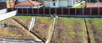
- It is also worth taking into account the characteristics of the soil on the site, its topography and the depth of soil freezing for optimal laying of the external pipeline.
Pipe selection
When laying the sewer system of a private house, round-section water flows with an internal diameter of 40 to 110 mm are used, made of polyvinyl chloride that is resistant to aggressive wastewater environments. Since various plumbing and household appliances are characterized by unequal volumes of wastewater, differing in consistency and composition, pipes with the following internal diameters are used:
- washbasins, kitchen sinks – 40-50 mm;
- bathtubs, shower trays – 50 mm;
- washing machines and dishwashers – 50 mm;
- urinals, bidets – 50 mm;
- toilets – 110 mm.
If a private residential building has 2 or more floors, the upper bathrooms are connected to the lower sewers using vertically located communications - risers - with an internal diameter of 110 mm.
For the yard drainage network, a special bright orange water flow is used, having a nominal passage of 110 or 160 mm.
Types of sewer networks
For those who have never created a sewerage project, it is worth knowing that professionals distinguish between two types of sewerage - internal and external. Accordingly, when executing the drawing, it is necessary to prepare two plans of the collector.
Internal sewerage includes all plumbing points located in the building. That is, on the plan drawing of the internal collector it is necessary to note:
- An example of the location of the toilet, sink, shower and all locations of household cleaning equipment;
- It is also worth drawing all the pipes coming from the plumbing points, indicating their footage for each element;
- The location of the riser is also indicated on the plan drawing.
The diagram should include all turns and bends of the pipeline with the application of transition elbows.
The sewerage project for the external system must also have a separate diagram on paper. This should include the following elements:
- The pipeline itself (its length from the exit from the house to the location of the septic tank);
- In the case of a large length of the collector, it is necessary to put on the plan drawing a diagram of the location of inspection and rotary wells.
According to the type of sewerage system, the system can be non-pressure or pressure.
In the first case, the sewerage system is gravity-flowing and drains waste through pipes spontaneously, due to the slope of the collector. This decision is usually made when installing a not very long pipeline to drain wastewater into a septic tank or provided that all plumbing points are located above the level of the horizontal riser.
Pressure sewer system. Here, a special fecal pump with a grinder helps transport wastewater. Such a system is installed if, for some reason, all or several plumbing fixtures are located below the riser level. (Example: basement bathrooms). In addition, pressure sewerage is done if the pipeline has a large length from the house to the septic tank, and due to the characteristics of the soil, it is not possible to lay the collector at a nominal slope.
Septic tank
A septic tank is a sealed container divided into two or three sections, or a system of two or three separate containers.
A septic tank, like a storage tank, can be built from monolithic reinforced concrete or reinforced concrete rings, or laid out of brick. You can also order a ready-made septic tank from specialized companies, which is a solid plastic body, the internal space of which is divided by partitions.
Sections or separate containers are connected to each other by a pipe through which wastewater that has passed the purification stage flows from one section (container) to another.
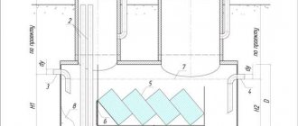
Septic tank operation diagram
In the first chamber, the sewage goes through the stage of initial rough cleaning: heavy particles settle to the bottom, light particles rise to the surface forming a fatty crust, and between these layers the water is clarified. Then the clarified water enters the second chamber for deeper cleaning.
A tee is placed on the inlet pipe , which will direct the incoming wastewater straight down without destroying the fat layer. The lower end of the tee must be constantly recessed into the wastewater, and the upper end must be above the surface of the drains in order to clear the tee from blockages without disturbing the fat layer. Above the tee, as a rule, ventilation is installed in the form of a piece of pipe, which should rise 70-80 cm above the ground surface so that the ventilation of the septic tank does not end up under snow in winter.
A single-chamber septic tank is used when the volume of wastewater is no more than 1 m3. Accordingly, a two-chamber septic tank is used when the volume of wastewater exceeds 1 m3.
Single chamber septic tank
In the case of a single-chamber septic tank , a tee is installed at the outlet of the septic tank, just like at the entrance, only a little lower. The tee at the outlet will allow only clarified water to be discharged outside, leaving a fatty layer in the septic tank. Clarified water from a single-chamber septic tank does not immediately enter the soil, but into special treatment facilities: filtration fields, filter trenches or filter wells, or into sand and gravel filters. And only after filtration does the purified water enter the soil.
Two-chamber septic tank
If you are designing a two-chamber septic tank , then instead of an outlet tee, a bypass pipe is installed at a depth of 50 cm from the bottom. It will ensure pumping of clarified water into the second chamber. In addition to the bypass pipe, a ventilation pipe is installed at a distance of 20 cm from the surface of the wastewater.
Any septic tank, be it single-chamber or double-chamber, is designed only in conjunction with treatment facilities , because... The septic tank carries out only rough mechanical treatment of wastewater.
Two-chamber septic tank with filter well
a three-chamber septic tank on your site, because... two chambers are enough to clean the wastewater to the required level, especially since the wastewater after the septic tank goes through a fine treatment stage in treatment facilities. In addition, to increase the level of purification, it is not at all necessary to increase the number of chambers, because wastewater is purified due to the time spent in the chamber; the longer the water settles, the better it will be purified. In this case, you should increase the volume of the chamber, and not their number.
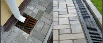
Features of the storm drainage system
The system for draining sediment from the site may contain a different number of elements intended for specific water collection areas. Typically, storm sewers include: storm water inlets, inspection and drain wells, and pipelines. The listed network links will be able to cope with the task provided that they have suitable volumes.
When planning the system, it is recommended to use a special tool - a calculator to calculate the amount of storm drains. After carrying out the calculations, you can easily select the dimensions of the elements that will be used to construct the drainage network.
Calculation of manifold hydraulics formulas and tables
The executive sewerage design for a home must also include a hydraulic calculation of sewer networks. This work is carried out in order to determine the optimal diameter of the pipeline, its slope and the speed of the wastewater in it. When calculating hydraulics, special formulas and tables are used. The data obtained will allow you to select the diameter of the pipes with maximum accuracy so that the drains fill it by two-thirds at a constant speed and at the same time air circulates in the system, which will ensure the removal of gases from the pipe. In addition, the hydraulic capacity of the sewer system should be improved in order to have a reserve of the diameter and slope of the collector in case of increased load on it.
So, in order to correctly fill out the formula for calculating the hydraulic capacity of the collector, it is necessary to find out the following formula values:
- DN - diameter of the outlet pipe;
- V is the average speed of wastewater in the pipeline;
- I is the hydraulic nominal slope of the collector;
- h/DN - pipeline filling level.
But these values most often do not always need to be calculated using the formula in full
Most often, the initial data is taken into account only after finding out the value of i or the value of h/Dn. Since all other data can be obtained by reading the SNiP tables for the calculation and execution of collector hydraulics
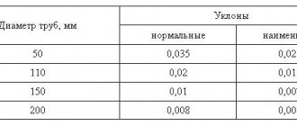
Thus, the value of V and the value of h/DN can be obtained from the table “Self-cleaning speed of sewage waste depending on the nominal diameter of the pipeline.” In addition, the minimum pipe slope according to SNiP regulations can vary from 0.8 to 0.7 mm per meter, provided the pipe diameter is within the range of 150-200 mm.
To calculate the hydraulic capacity of the sewer system, it is recommended to use the tables of F.A. and A.F. Shevelev and the Lukin tables. These help to calculate almost all the data for correct calculations. So, convenient for carrying out calculations are:
- The table called “Calculation of wastewater flow, liters per second”;
- Table “Pipe throughput depending on the pressure of the transported liquid”;
- Tables of the capacity of free-flow pipes for the sewer system;
- Capacity tables for pressure sewers.
To calculate the volume of transported wastewater through the collector, you must use the formula:
q=a•v.
The formula values are interpreted as follows:
- a is the cross-section of water flow in the pipe;
- v is the speed of wastewater transportation, calculated in m/s.
To calculate the speed of movement of wastewater, use the formula
v= C√R*i,
the values are interpreted as follows:
- R—hydraulic radius;
- C is the coefficient of wetting of the inner surface of the pipe;
- i is the slope of the collector.
To derive the value of the hydraulic slope of a pipe, use the formula
i=v2/C2*R.
Here it is enough to substitute all the values obtained by the method of earlier calculations or taken from the corresponding tables according to the expected pipe diameter. The wetting coefficient of the inner surface of the collector is calculated as follows:
С=(1/n)*R1/6.
Here n is the roughness coefficient, varying from 0.012 to 0.015 depending on the pipeline material.
How much water flows?
A country house must have a kitchen, no matter inside or as a separate building; in addition, it is impossible to do without a bathroom, while a toilet can be built directly above the cesspool. Moreover, if a certain amount of water enters the home, limited by the pressure in the pipes and, accordingly, the pressure, then much more can be drained. A striking example is a filled Jacuzzi bathtub, in which at least a couple of hundred liters of water accumulates.
If the drain capacity is insufficient, when draining from such a large tank, the liquid will certainly find other ways, for example, splashing out of the kitchen sink. In general, it is quite simple to find out the volume of drained water; there are consumption standards per person, summarized in tables, one of which will be given below.
All that remains is to find out what the volume of the sump should be, where all the drains will go along with human waste products. First, you need to decide what exactly you will have on your site - a cesspool or a septic tank. The first option is cheaper, although it requires regular cleaning - according to the standards for 1 person living in the house, you need to allocate a volume equal to 0.7 cubic meters and dig a couple of cubes for reserve.
| Purpose of expenditure | Average water consumption day, liters | Day of greatest water consumption, liters | ||
| for 1 person | for 4 people | for 1 person | for 4 people | |
| Tea (3 times a day) | 1,2 | 4,8 | 1,2 | 4,8 |
| First | 0,5 | 2 | 0,5 | 2 |
| Second (3 times a day) | 1 | 4 | 1 | 4 |
| Washing vegetables and fruits | 4 | 16 | 4 | 16 |
| Washing dishes (3 times a day) | 12 | 48 | 12 | 48 |
| Washing | 10 | 40 | 10 | 40 |
| Shower | 90 | 360 | – | – |
| Toilet | 25 | 100 | 25 | 100 |
| Bath | – | – | 150 | 600 |
| Wash | – | – | 20 | 80 |
| Cleaning of the apartment | 2 | 8 | 6 | 24 |
| Total | 145,7 | 582,8 | 229,7 | 918,8 |
| 10% (hand washing, etc.) | 14,37 | 57,48 | 22,97 | 91,88 |
| TOTAL | 160,07 | 640,28 | 252,67 | 1010,68 |
Arrangement of rainwater drainage rules and recommendations
The main purpose of calculating storm sewers is to determine the diameter and slope of the pipe in accordance with the amount of precipitation falling in a particular area. If the pipeline capacity is insufficient, the efficiency of the sewer network is significantly reduced, which increases the likelihood of flooding the area during heavy rains.
The drainage system is an important element of any construction project.
All work on the arrangement of storm sewerage is regulated by SNiP. In addition to hydraulic calculations, for proper operation of the system it is necessary to adhere to the following recommendations:
- Domestic sewage and industrial waste should not be discharged through storm drains.
- The place where wastewater is discharged into a natural reservoir must be agreed upon with the sanitary and epidemiological service, as well as with water bodies protection authorities.
- Surface water from the territory of private farms can be directed to the central sewer network without preliminary treatment. For industrial enterprises, wastewater must pass through additional treatment facilities.
- The ability to receive atmospheric precipitation from the territories of private and industrial facilities by the city sewerage system is determined by the capacity of the central network and the productivity of treatment facilities.
- Surface water drainage, if possible, should be organized in gravity mode.
- For large settlements and production sites, it is necessary to provide closed drainage systems. For low-rise suburban properties, the use of an open sewer network is allowed.
In private homes, open and closed rainwater drainage systems are often combined