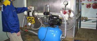
Imagine that to get water at your dacha you can simply open the tap. That there is no need to fill containers with buckets for basic hygiene procedures, cooking, and cleaning. To do this, you just need to install pumping equipment with a pressure sensor, but first you need to understand its structure, don’t you agree?
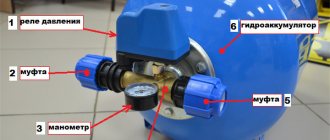
Our article will introduce you in fine detail to the pressure switch for the pumping station. You will learn how the device works, how it activates and stops pumping. We describe in detail the popular options for pressure sensors and how to adjust them.
The material lists technological nuances and methods for setting up the relay. The information presented is ideally complemented by useful diagrams, photos and video applications.
The role of the pressure switch in the water supply system
The device, small in size, belongs to the group of automation systems servicing pumping equipment. Its functionality is only possible in conjunction with a hydraulic accumulator.
Despite its small size, the relay performs a number of important functions:
- allows all devices to function in the specified mode;
- Reacts sensitively to changes in on/off thresholds;
- activates and stops the pump when critical values are reached.
Simply put, it regulates the automatic pumping process of water in independent water supply schemes with a membrane tank. The adjustment is made during the switching of electrical circuits when two pressure parameters are reached in the system, accepted as the upper and lower limits.
When purchasing a pumping station, you receive a set of equipment, part of which is a pressure switch. Externally, models of different brands and series are similar, but may differ in shape, size, body color, setting method and location.
When assembling automation yourself, you need to study the characteristics of the devices and choose the most suitable ones for a particular system.
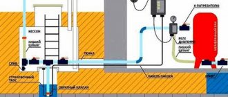
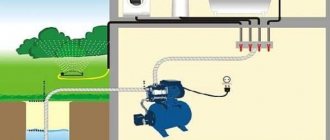
Layout of devices involved in organizing water supply to a private house from a well or borehole. The relay controls the operating pressure in the network, and the pressure gauge displays the current parameters
The devices are adapted for convenient installation and maintenance of the pumping station. Most often, they are secured with a fitting at the inlet of the hydraulic accumulator, but they can also be mounted in the pipe of the cold water system in close proximity to the device.
Image gallery
Photo from
Original Grundfos pressure switch
Relay with integrated pressure gauge AL-KO
Domestic pressure switch Whirlwind
Gardena brand equipment for the garden
Choosing an installation location
For correct operation of the equipment, the pressure switch must be connected to the pump in such a way as to avoid the influence of turbulence and sudden pressure changes when the pumping equipment is turned on and during its operation. The best place for this is in the immediate vicinity of the hydraulic accumulator.
Before installing the pressure switch, pay attention to the operating mode recommended by the manufacturer, in particular, the permissible temperature and humidity values. Some models can only work in heated rooms.
In the classic scheme for connecting a pressure switch to a deep-water pump for an autonomous water supply, the following equipment is installed in front of the relay:
- pumping unit,
- check valve,
- pipeline,
- flow shut-off valve,
- drainage to the sewer,
- filter for preliminary (coarse) cleaning.
When using many modern models of surface-type pumping units, installing a water pressure switch for a pump can be much simpler: block installation is carried out when the relay is installed together with the pump. The pumping unit has a special fitting, so the user does not need to independently search for the most suitable installation location. The check valve and filters for water purification in such models are often built-in.
Connecting the pressure switch to a submersible pump can also be done by placing the hydraulic accumulator in the caisson and even in the well itself, since waterproof design of the control equipment is often required and the operating conditions of the pressure switch may allow its location in such places.
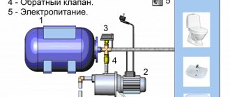
The connection diagram for a pressure switch and a pumping station with a surface pump differs slightly from the diagram with a submersible unit in the sequence of arrangement of some elements
Obviously, the choice of installation method and location depends on the design of the equipment; usually all recommendations in this regard are indicated by the manufacturer in the accompanying documentation.
Design and principle of operation
The pressure control relay has a simple dismountable design, thanks to which the user can independently adjust the operation of the accumulator, narrow or expand the parameters.
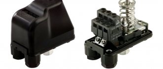
The internal parts are housed in a durable plastic case that resembles an irregularly shaped box. It has a smooth surface and only 3 external working elements: two coupling clamps for electrical cables coming from the network and the pump, and a ¼, ½, 1 inch metal pipe for connecting to the system. The thread on the pipe can be either external or internal.
To remove the device body, you need to arm yourself with a flat screwdriver and slowly and carefully unscrew the screw recessed into the plastic, located above the axis of the large spring
Inside there is a base to which the working elements are attached: large and small springs with adjusting nuts, contacts for connection, a membrane and a plate that changes its position depending on the increase/decrease in pressure parameters in the system.
Image gallery
Photo from
Terminals for connecting the ground wire
Terminals for connecting phase and neutral
Large spring and its purpose
Small adjustment spring
The contacts of two electrical circuits, closed when the maximum pressure parameters are reached, are located under the springs, which are fixed to a metal plate. When the pressure increases, the membrane of the hydraulic tank is deformed, the pressure inside the bulb increases, and the mass of water presses on the plate. That, in turn, begins to act on a large spring.
When compressed, the spring is activated and opens the contact that supplies voltage to the motor. As a result, the pumping station is switched off. With a decrease in pressure (usually in the range of 1.4 - 1.6 bar), the plate returns to its original position and the contacts close again - the motor begins to work and pump water.
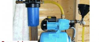
When purchasing a new pumping station, it is recommended to test the equipment to ensure that all components are working properly. Checking the performance of the relay occurs in the sequence outlined below. As an example, the Haitun PC-19 model.
Image gallery
Photo from
Pumping station with automation unit
The pressure gauge is built into the relay housing
Equipment operation monitoring
Dry running alarm
Mechanical models do not have an indication or control panel, but they can be equipped with a forced activation button. It is necessary to make it function.
Top 3 models
Users purchase several models of mechanical, switch, electronic ones more often than others.
For apartment
Popular:
- Regulator PM 5-3W, manufacturer UNI-FITT, Italy. The device combines a mechanical detector, a pressure gauge and a five-pin fitting. The maximum switching power is 1.5 kW. Adjustment limits are from 1 to 4.5 bar.
- Pointer relay RDS-M, manufacturer Aquacontrol, Russia. Provides protection against dry (idle) running. The connecting size is 1/2″. Maximum pressure - up to 10 bar.
- Electronic relay RDE-10 Universal-1.5 G1/2″, manufacturer Aquacontrol, Russia. Protects against dry running. Automatically turns on the pump after stopping. The connecting size is 1/2″. Maximum pressure - up to 6 bar. Rated switching current - 6.9 A.
For a private home
Often bought:
- Mechanical relay Aqu6352, manufacturer Aquario, China. The connecting size is 1/4″. Rated switching current - 16 A. Adjustment limits - from 1 to 5 bar.
- Mechanical pressure switch MDR 21. Manufacturer: Condor, Germany. The connecting size is 1/2″. Maximum switching power is 2.2 kW.
- Pointer relay RDS-30, manufacturer Aquacontrol, Russia. The connecting size is 1/2″. Switching power - 1.5 kW. Performs idle speed protection.
Criteria for selecting a relay for a pump
There are many universal models that are sold separately from pumping stations and can be used to assemble a system with your own hands. When purchasing a relay or automation unit, you must rely on the characteristics of the device. They can be found in the technical documentation.
It is important that the relay’s capabilities match the characteristics of the rest of the equipment.
Before purchasing an automation unit or relay, carefully study the technical data of the model. In most cases, they are standard: nominal pressure from 1.5 atm, maximum - 3 atm.
You should start from the nominal pressure, but the upper limit of the operating pressure is also important. It is necessary to take into account electrical indicators and maximum water temperature. A mandatory parameter is the IP class, which indicates dust and moisture protection: the higher the value, the better.
Connecting thread sizes are indicated in inches: for example, ¼ inch or 1 inch. They must match the dimensions of the connection fitting. The dimensions and weight of the devices themselves are approximately the same and are secondary characteristics.
It should also be remembered that there are built-in and remote models. Most commercially available devices are universal: they can be connected directly to the hydraulic tank or mounted on a pipe.
Electronic relays have the same functions as mechanical ones: they are responsible for the water supply and protect the pump mechanism from dry running. They are more capricious than simple models and are sensitive to suspended particles in the water. To protect the device, a mesh dirt filter is installed in front of its connection point.
In essence, the electronic device is an automation unit with a convenient display and a system of buttons that makes it possible to make adjustments without disassembling the device
One of the differences from the traditional model is the delay in turning off the pump. If, when the pressure increases, the mechanical device responds quickly, the electronic analogue turns off the equipment only after 10-15 seconds. This is explained by a careful attitude towards equipment: the less often the pump is turned on/off, the longer it will last.
Some switch models, as well as automation units, operate without a hydraulic accumulator, but their functionality is limited to simpler use. Suppose they are great for watering the garden or pumping liquid from one reservoir to another, but are not used in the home water supply system.
At the same time, the technical characteristics of the devices are the same as those of traditional relays: factory setting is 1.5 atm, shutdown threshold is 3 atm, maximum value is 10 atm.
Functions, purpose, types
In the water supply system of a private house without a hydraulic accumulator, the pump turns on whenever water flows somewhere. These frequent starts lead to wear and tear on the equipment. And not only the pump, but the entire system as a whole. After all, every time there is an abrupt increase in pressure, and this is a water hammer. To reduce the number of pump starts and smooth out water hammer, a hydraulic accumulator is used. The same device is called an expansion or membrane tank, a hydraulic tank.
Purpose
We found out one of the functions of hydraulic accumulators - to smooth out water hammer. But there are others:
- Reducing the number of pump starts. There is some water in the tank. With a small flow rate - wash your hands, wash yourself - water flows from the tank, the pump does not turn on. It will turn on only when there is very little left.
- Maintaining stable pressure. This function requires one more element - a water pressure switch, but they maintain the pressure within the required limits.
- Create a small supply of water in case of power outage.
It is not surprising that most private water supply systems have this device - there are many advantages from its use.
The hydraulic accumulator is a tank made of sheet metal divided into two parts by an elastic membrane. There are two types of membrane - diaphragm and balloon (bulb). The diaphragm is attached across the tank, a pear-shaped cylinder is secured at the inlet around the inlet pipe.
According to their purpose, they are of three types:
- for cold water;
- for hot water;
- for heating systems.
Hydraulic tanks for heating are painted red, tanks for water supply are painted blue. Expansion tanks for heating are usually smaller in size and lower in price. This is due to the membrane material - for water supply it must be neutral, because the water in the pipeline is potable.
Depending on the type of arrangement, hydraulic accumulators can be horizontal or vertical. Vertical ones are equipped with legs; some models have plates for hanging on the wall. It is the elongated upward models that are most often used when independently creating water supply systems for a private home - they take up less space. The connection of a hydraulic accumulator of this type is standard - through a 1-inch outlet.
Horizontal models are usually equipped with pumping stations with surface-type pumps. Then the pump is placed on top of the tank. It turns out compact.
Principle of operation
Radial membranes (in the form of a plate) are used mainly in gyroaccumulators for heating systems. For water supply, a rubber bulb is usually installed inside. How does such a system work? As long as there is only air inside, the pressure inside is standard - the one that was set at the factory (1.5 atm) or that you set yourself. The pump turns on, begins to pump water into the tank, and the pear begins to increase in size. Water gradually fills an increasingly larger volume, increasingly compressing the air that is located between the wall of the tank and the membrane. When a certain pressure is reached (usually for one-story houses it is 2.8 - 3 atm), the pump is turned off, and the pressure in the system stabilizes. When you open a tap or other water flow, it comes from the accumulator. It flows until the pressure in the tank drops below a certain level (usually about 1.6-1.8 atm). After which the pump turns on, the cycle repeats again.
If the flow rate is large and constant - you are filling a bathtub, for example - the pump pumps water in transit, without pumping it into the tank. The tank begins to fill after all the taps are closed.
A water pressure switch is responsible for turning the pump on and off at a certain pressure. In most hydraulic accumulator piping schemes, this device is present - such a system operates in optimal mode. We’ll look at connecting the hydraulic accumulator a little lower, but for now let’s talk about the tank itself and its parameters.
Large tanks
The internal structure of hydraulic accumulators with a volume of 100 liters and above is slightly different. The pear is different - it is attached to the body both at the top and bottom. With this structure, it becomes possible to fight the air that is present in the water. To do this, there is an outlet in the upper part into which you can connect a valve for automatic air release.
Reasons for customization
The dismountable design of the device and the setup instructions were not invented in vain. Factory parameters rarely meet the requirements of the water supply system, as well as the volume of the accumulator.
Before the relay correction procedure, you must make sure that the hydraulic accumulator is in good working order and that the water supply system to the house is functioning properly, otherwise you may set the operating parameters incorrectly
Using settings, you can not only “adjust” the upper and lower limits to the optimal values, but also make the operation of the equipment more gentle - for example, reduce the number of pump starts/stops. To do this, it is enough to slightly increase the range between operating pressures - delta.
You may also encounter incorrect settings of the factory model. If the delta is incorrectly coordinated and made too small, the pump will constantly turn on and off, reacting to a minimal increase in parameters.
Causes of pumping station malfunctions and do-it-yourself solutions
The pumping station is the heart of the water supply system for a cottage or private home. This simple but functional device, capable of providing good pressure, can be purchased at retail by choosing the model that has the optimal characteristics. Pumping stations, when installed correctly, are reliable, stable, and do not require periodic maintenance. However, failures in their operation inevitably occur over time. Every owner of such equipment needs to know the malfunctions of a pumping station and how to eliminate them. In some cases, it is quite possible to carry out repairs yourself.
Recommendations for adjusting the device
By manipulating the springs, you can change the pump shutdown threshold, as well as adjust the volume of water in the accumulator tank. It is generally accepted that the larger the delta, the larger the volume of liquid in the tank. For example, with a delta of 2 atm. the tank is 50% filled with water, with a delta of 1 atm. – by 25%.
To achieve a delta of 2 atm, you need to set the lower pressure value, for example, to 1.8 atm, and the upper one to 3.8 atm, changing the position of the small and large springs
First, let's remember the general rules of adjustment:
- to increase the upper response limit, that is, increase the shutdown pressure, tighten the nut on the large spring; to reduce the “ceiling” - weaken it;
- to increase the difference between the two pressure indicators, tighten the nut on the small spring; to reduce the delta, loosen it;
- moving the nut clockwise means increasing the parameters, counter-clockwise means decreasing them;
- To set up, you need to connect a pressure gauge, which shows the initial and changed parameters;
- Before starting the adjustment, you need to clean the filters, fill the tank with water and make sure that all pumping equipment is working.
All adjustment actions are carried out only after testing the system and detecting low performance or obvious errors in operation. It also happens that the station stops working due to a blockage that has clogged the filter or one of the narrow pipes. There is another article on our website that describes the process of adjusting the pressure switch in more detail - follow the link to read the material.
What is a pumping station
A pumping station is a complex of a pump, a hydraulic accumulator-compensator and automatic control. Such a system is capable of:
- supply water to the home network and maintain the required level of pressure in it;
- provide pressure regulation to supply water to the second floor or satisfy the maximum level of consumption;
- protect the pipe system from water hammer, which can lead to the destruction of parts of the water supply system;
- store a certain supply of liquid inside the accumulator, which will be useful when the power supply is turned off or the water source is depleted.
The specific engineering solution for a pumping station may vary. For example, a submersible pump is used for deep wells. When drawing water from a shallow well, a surface pump is used. The volume of the hydraulic accumulator may vary, depending on the consumption parameters calculated for a private home.
Practical examples of relay configuration
Let's look at cases when turning to adjusting the pressure switch is really necessary. This usually happens when purchasing a new device or when frequent pump shutdowns occur.
You will also need to configure it if you received a used device with lost parameters.
Connecting a new device
At this stage, you should check whether the factory settings are correct and, if necessary, make some changes to the operation of the pump.
Image gallery
Photo from
Stage 1 – equipment preparation
Stage 2 - adjusting the switching value
Stage 3 - adjusting the shutdown value
Stage 4 – testing the system operation
To track the progress of work, it is recommended to write down all received data on a piece of paper. In the future, you can return the initial settings or change the parameters again.
The pump stopped turning off
In this case, we forcibly turn off the pumping equipment and proceed in the following order:
- We turn it on and wait until the pressure reaches its maximum level - let's say 3.7 atm.
- We turn off the equipment and lower the pressure by draining water - for example, to 3.1 atm.
- Lightly tighten the nut on the small spring, increasing the differential value.
- We check how the cut-off pressure has changed and test the system.
- We configure the optimal option by tightening and loosening the nuts on both springs.
If the reason was due to incorrect initial settings, it can be solved without buying a new relay. It is recommended to regularly, once every 1-2 months, check the operation of the pressure switch and, if necessary, adjust the on/off limits.
Situations that do not require adjustment
There can be many reasons when the pump does not turn off or turn on - from a blockage in the communications to engine failure. Therefore, before you start disassembling the relay, you should make sure that the rest of the pumping station equipment is working properly.
If everything is fine with the other devices, the problem is in the automation. Let's move on to inspecting the pressure switch. We disconnect it from the fitting and wires, remove the cover and check two critical points: the thin pipe connecting to the system and the contact block.
Image gallery
Photo from
The connection pipe to the hydraulic tank is clogged
Cleaning the relay inlet
Electrical contacts are clogged
Cleaning the contact block
If cleaning measures did not help, and adjusting the position of the springs was also in vain, most likely the relay is no longer suitable for further use and should be replaced with a new one.
Suppose you come across an old but working device. Its adjustment occurs in the same order as setting up a new relay. Before starting work, make sure that the device is intact, disassemble it and check that all contacts and springs are in place.
Water supply without accumulator
If you exclude the hydraulic accumulator from the water supply scheme, then two options are possible:
- using a pump to supply water directly to water collection points;
- connecting a storage tank.
Both options are actively used, but the first is optimal for irrigation systems with a small volume of liquid, and the second is most appropriate when you need to provide water to a shower, kitchen faucet - that is, consumers inside the house.
Connecting the pump directly
One of the options is an expanded irrigation system for a personal plot. It is fully automated. To set the on/off time, connect the controller. Solenoid valves can be installed on each individual line so that they can be operated separately.
Approximate scheme of automatic watering of a summer cottage. Transportation of liquid from a well or well is carried out through pipes with a diameter of 19 mm (central) and 16 mm (branches) (+)
- we place the pipes on the surface of the earth according to a pre-designed diagram and connect them with fittings;
- we install sprinklers, drip systems, watering hoses;
- we equip a pumping group - a surface unit and a pressure switch;
- connect the water supply, test the system for leaks;
- if all is well, we dig trenches 30 cm deep, build a drainage cushion from crushed stone and sand, lay the pipeline and fill it up;
- We carry out repeated testing to check the tightness, check the performance of all lines;
- connect the controller and rain sensor;
- We check the operation of all elements of the system.
If the throughput is small, we set up alternate operation of the lines. This is a complex circuit that requires knowledge of how to configure the equipment. The simplest is a regular “Baby” type pump with watering hoses connected to it.
Scheme with storage tank
With the advent of technologically advanced hydraulic accumulator stations, the scheme has become less popular, but is still in use. It is simple and differs in that there is a storage tank between the pump and the water collection points.
Diagram of a water supply system with a storage tank. To ensure the movement of water through the pipes at a certain speed and pressure, an additional circular pump is installed
After the filtration system, a storage tank is installed, and a pipe (or pipes) goes from it to the water collection points.
Storage tank - any tank of suitable volume. Previously, they used galvanized metal tanks, now they use plastic containers of various configurations. They are equipped with one inlet pipe for supplying water from a well, and two outlet pipes for distribution to consumers and drains.
The top of the tank is covered with a hinged lid that protects the liquid from debris and dust. By removing the lid, you can analyze the condition of the tank and the water stored in it. In case of severe contamination, the liquid is released through the drain pipe and the tank is washed.
The main controlling element is the float mechanism. As soon as the water level reaches the maximum level, the inlet pipe is closed and the supply to the tank stops. At a low level, on the contrary, the inlet opens and water begins to flow into the tank.
Plastic storage tank installed in the attic. It is lighter in weight than a metal container, so it is much more convenient to install. To prevent the water from freezing, in the northern regions the walls of the tank are insulated
The advantage of using a storage tank: there is always a supply of water, which is supplied under low pressure, even if all pumps are turned off. The downside is that it's difficult to install. Large tanks require space and a base that can support their weight.
In the case of installing systems for year-round operation, the attic, or at least the tank itself, located in an unheated attic space, must be insulated.
Automation and safety equipment
To understand how to quickly diagnose and troubleshoot problems, you need to know about the pumping station controls and the principle of its operation.
- The causes of pump failure include dirt and mechanical suspensions. Therefore, a coarse filter must be installed on the supply pipe.
- To avoid problems when the station does not pump water, it is necessary to install a return valve on the supply pipe. It will prevent water from going back into the well and prevent air from entering the working circuit.
- The pressure gauge is the main device for monitoring the operation of the station and the condition of the water supply network. Mounted on the outlet pipe, it shows the pressure and allows for instant assessment.
- Pressure parameters are adjusted using the appropriate relay. It is included in the list of accumulator components and is responsible for turning the supercharger motor on and off.
Everything works quite simply. During initial start-up, the pump pumps water into the accumulator. Inside it there is a membrane, a rubber bulb. Filling with water and expanding, it compresses the air in the container. The sensor monitors the increasing pressure. When the set level is reached, the relay turns off the pump. The pressure gauge shows the pressure reached in the water supply. When a tap is opened inside the house, water enters the network, taken from the accumulator bulb. When the pressure drops below the configured limit, the relay activates the pump and the cycle repeats.
Malfunctions and methods for their elimination
Unfortunately, over time, the pumping station may begin to operate abnormally. It is impossible to avoid this, since there are no eternal materials, oxidation and leakage processes constantly occur, in addition, dirt accumulates in the station components during operation. If the water supply system begins to work poorly, you should slowly check the condition of the pump unit and eliminate shortcomings that you can deal with yourself.
The pump does not turn on
There may be several reasons why the pump does not respond to start commands and does not start.
- The condition of the power supply network is checked. The integrity of the power cable is assessed (there should be no insulation wear or fractures).
- The network voltage is tested. When low, the pump does not work.
- The quality of the connection of contact groups (sockets, functionality of circuit breakers) is checked.
If the checks show that everything is in order, but cleaning the contacts did not bring results, the problem may be in the operation of the pressure sensor: it does not work. The hydraulic accumulator control unit is partially disassembled, the condition of the relay (contacts, springs) is checked, and if necessary, the parts are cleaned of corrosion and dirt.
If the pump does not start after the measures taken, the problem may be combustion of the windings. Such repairs cannot be carried out at home.
The engine makes a hum, but the pump does not start
If the station is idle for a long time, its owner may encounter a situation where, when turned on, the pump hums, but does not pump. The reason is the turbine impeller sticking, sticking to the housing. This problem is resolved as follows.
- The station is disconnected from the power supply; it is necessary to close the inlet and outlet pipes.
- Using drainage, it is necessary to drain the water from the supply system.
- The pumping station is being partially dismantled.
- The impeller is rotated manually or removed.
- It is recommended to remove the impeller from the pumping station to thoroughly clean the internal surfaces of the housing and the part itself.
What to do if the pumping station is frozen
As a conclusion, it is worth touching on the issue of resuscitation of the pumping station. Despite clear instructions for operating equipment only in a warm room, situations when the pumping station freezes do occur. Water can turn into ice:
- inside the underwater pipe to the house, at the border of soil freezing;
- in supply pipes coming from a well or well;
- in the part of the pipeline immediately adjacent to the pump:
- in the most difficult cases - inside the mechanics of the pump.
If, during an inspection of the condition of pipes and the pumping station, cracks in metal, plastic, and structural elements are found, the repair is reduced to disassembling the equipment, part of the water supply network and replacing damaged parts and pipes. However, when a liquid freezes, it does not immediately rupture the metal, and there is a non-zero chance of saving the equipment.
Important! Before defrosting work, the station must be disconnected from the water supply network, if possible, open the shut-off valves or unscrew the flanges of the problem area, creating vanishing points for expanding water.
The procedure for handling pipes depends on their type, as well as the tools and tools available. The connections can be thawed with boiling water, and the steel pipes can be heated with a blowtorch. The temperature increase process must be gradual so as not to cause damage due to sudden changes.
The most effective, but time-consuming way to defrost the pump mechanics is to install incandescent lamps. The heating object must be placed in some limited space, for example, surrounded by a box turned upside down, the walls of which are 200 millimeters or more away from the heat source. After this, the lamp turns on, its power should be at least 100 watts.
The pipes can be heated with a heating cable, which can be easily purchased at any store that sells electric heating systems. By wrapping the frozen area and applying 220V voltage to the cable, you can quickly and safely defrost the system. Good results from using this method are also observed when working with pump mechanics.