It is difficult to imagine the operation of an individual water supply system without automatic elements - in their absence, the pump would continuously pump water, and you would have to turn it on and off manually when filling the main line. Automatic devices for controlling the operating modes of electric pumping equipment respond to the physical parameters of the liquid in the line or its absence; the most used of them is the water pressure sensor in the water supply system.
A device that responds to pressure is installed in an individual water supply system with a submersible electric pump or a surface pumping station; in complex automatic control units, the device is built into a module together with other devices. When installing a pressure switch into a water main with your own hands, it is important to know the rules for its connection and settings, which allow you to set the thresholds for operation and shutdown of electric pumps during water supply.
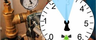
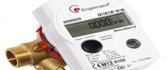
Rice. 1 Pressure switches for water supply systems - varieties
What it is?
A sensor is a device that responds to changes in pressure and converts the received readings into a signal for water intake equipment.
The device is placed between the pump and the accumulator. The settings set the permissible pressure range.
The device ensures continuous operation of the home water supply:
- upon reaching the upper limit, it opens the circuit, stops water intake,
- when the pressure drops to a lower level, the pump resumes operation.
Electrical connection diagram
Depending on the needs of the user and his financial capabilities, you can choose one of the methods of connecting the deep pump to the electrical network.
Without automation
Without auxiliary control devices, the pump is connected using a pre-installed electrical outlet with a grounding contact. The pump is also grounded. For this purpose, the main bus of the house is used, connecting to the existing ground loop of the building.
A three-core cable is used to supply electricity to the outlet. The power supply voltage of the submersible pump is 220V. 380-volt or 150-volt outlets cannot be used.
Via pressure switch
To reduce the cost of a set of pressure equipment, you can use a connection diagram for a well pump only with a pressure switch without a control unit. The device turns off the pump when the pressure reaches a maximum, and starts it when the pressure drops to a minimum.
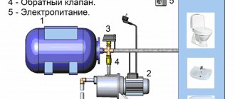
Using control unit
When selecting an automation model, you first need to find out what protective system is already installed in the pump by the manufacturer. Modern devices are already protected from overheating and idle operation. Sometimes the equipment is equipped with a float mechanism. Taking this data into account, you can choose one of three automation options - simple, with a second or third generation electric control unit.
The simplest protection is most often used for automatic water supply. The control unit here is assembled from three devices:
- Dry running blocker. It will turn off the device, which operates without water, preventing overheating. Sometimes the additional installation of a float switch is allowed. It performs the same functions, turning off the pumping equipment when the water level drops, preventing it from overheating. The devices may seem primitive, but they provide effective protection for the electric motor.
- Hydraulic accumulator. Without it, it will not be possible to provide automatic water supply. The hydraulic tank works as a water storage tank. Inside there is a working mechanism - a diaphragm.
- Pressure switch equipped with a pressure gauge. This device allows you to configure the operation of relay contacts.
It is not difficult to equip pressure equipment with simple automation with your own hands. The principle of operation of the system is simple: as water flows, the pressure in the hydraulic tank decreases. When the minimum value is reached, the relay starts the pressure equipment, which pumps water into the storage tank. When the pressure in the hydraulic accumulator reaches its maximum, the relay device turns off the installation. As water is consumed, the cycle repeats.
The pressure limits in the storage tank are adjusted using a relay. In the device, using a pressure gauge, the minimum and maximum response parameters are set.
In second-generation automation, the connection is made through an electrical unit with a set of sensors. They are mounted directly on pressure equipment, as well as inside the water supply network, and allow the system to function without a hydraulic tank. The impulse from the sensors goes to the electronic unit, which controls the system.
Operation of pressure equipment with this scheme for connecting a submersible well pump to automation:
- Liquid accumulates only in the water supply where one of the sensors is installed.
- When the pressure drops, the sensor sends a pulse to the control unit, which starts the pump.
- After reaching the required pressure of the water flow in the water supply, the pump is turned off according to a similar scheme.
To install such automation, you will need basic knowledge of electrical engineering. This and the previous protection work almost identically - based on water pressure. However, the electric unit with sensors is more expensive, which is why it is not so popular among consumers. Even when using automation, you don’t have to use a hydraulic tank, although if there is a power outage, you won’t be left without water. There is always a reserve left in the drive.
Third generation automation is reliable, high quality and expensive. Its installation allows you to significantly save on electricity due to ultra-precise tuning of the electric motor. The connection diagram for advanced automation to a deep well pump is very complex, so you should contact a professional to connect it. But it provides complete protection of the motor from various breakdowns, for example, overheating during dry running or burning of the windings during power surges.
The unit operates from sensors without a hydraulic tank. Efficiency is achieved through fine adjustments.
Why is it installed?
The controller is a necessary link in the autonomous water supply system; it provides the necessary water pressure for the normal operation of plumbing fixtures and extends their service life. But with increased flow, the pressure in the system drops, and the pump operates at its limit.
A more comfortable option for controlling water supply is a combination of a sensor and a frequency converter, a device for maintaining constant pressure.
Advantages of installing an inverter:
- constant pressure in the water supply system;
- the required volume of water without limiting the pump load;
- preventing temperature surges in the heating tank due to pressure changes;
- smooth start and stop of the pump, which increases the service life of the equipment and prevents water hammer.
The pressure decreases only at a significant flow rate, when there is not enough pump power. But even in this case, the system’s performance will be stable at the level that the water intake equipment is capable of.
Connecting the water pressure switch
The water pressure switch for the pump is connected to two systems at once: electricity and water supply. It is installed permanently, since there is no need to move the device.
Electrical part
To connect a pressure switch, a dedicated line is not required, but is desirable - there is a greater chance that the device will work longer. A cable with a solid copper core with a cross-section of at least 2.5 square meters must run from the shield. mm. It is advisable to install a combination of automatic + RCD or difavtomat. The parameters are selected based on current and depend more on the characteristics of the pump, since the water pressure switch consumes very little current. The circuit must have grounding - the combination of water and electricity creates a zone of increased danger.
Connection diagram of the water pressure switch to the electrical panel
The cables are inserted into special inputs on the back of the case. Under the cover there is a terminal block. It has three pairs of contacts:
- grounding - the corresponding conductors coming from the panel and from the pump are connected;
- line or “line” terminals - for connecting the phase and neutral wires from the panel;
- terminals for similar wires from the pump (usually on the block located above).
Location of terminals on the body of the water pressure switch
The connection is standard - the conductors are stripped of insulation, inserted into the connector, and tightened with a clamping bolt. By pulling the conductor, check whether it is securely clamped. After 30-60 minutes, the bolts can be tightened, since copper is a soft material and the contact may weaken.
Pipeline connection
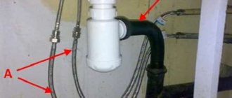
There are different ways to connect a water pressure switch to the plumbing system. The most convenient option is to install a special adapter with all the required outputs - a five-pin fitting. The same system can be assembled from other fittings, it’s just that it’s always easier to use a ready-made version.
It is screwed onto the pipe on the back of the housing; a hydraulic accumulator, a supply hose from the pump and a line that goes into the house are connected to the other outputs. You can also install a mud pan and a pressure gauge.
An example of tying a pressure switch for a pump
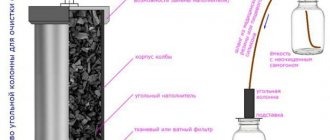
A pressure gauge is a necessary thing - to monitor the pressure in the system, monitor the relay settings. A mud trap is also a necessary device, but it can be installed separately on the pipeline from the pump. In general, a whole system of filters for water purification is desirable.
With this scheme, at high flow rates, water is supplied directly to the system - bypassing the hydraulic accumulator. It begins to fill after all the taps in the house are closed.
Design and principle of operation
Based on the principle of operation, there are controllers that control the pump by pressure or flow:
A mechanical sensor consists of a diaphragm, a system of mechanisms and levers that turn the pump on or off when the membrane deviates beyond the upper or lower limits of the set range.
Electronic, dial gauges and control units operate on the same principle; they differ in the type of signal that the device generates.- Sensors that control pumping equipment along the flow maintain approximately constant pressure with uniform water intake.
When all taps are closed, the pump pumps water to the maximum pressure point and turns off. A hydraulic accumulator is often included in the flow control unit; in this case, it has a small volume (0.2-0.6 l) to dampen water hammer without accumulation. For a flow-controlled sensor, the power of the water intake equipment is carefully calculated so as not to create excess pressure in the tank, or a reducer is installed to protect the system from extreme pressure. - When the water supply is stopped, to maintain the functionality of the water intake equipment, it is convenient to have a dry running sensor with the opposite principle of operation. The device will turn off the pump as soon as the water pressure in the system drops below the set pressure. Has a reset button or lever for forced start.
Connecting a high-frequency converter greatly improves controllability.
The inverter changes:
- the frequency of the current supplied to the pump motor,
- balances the rotation,
- pumps the volume of water that is currently consumed.
The sensor monitors system performance. The automation constantly maintains a given pressure level, which can be adjusted.
We connect the relay to the water main
You need to connect the pressure switch to water first, and to electricity second.
Setting up the relay is the very last, third stage. Let's assume that everything turned out great and we found that piece of pipe with a thread to which we need to screw the pressure switch. Do you know how to make reliable threaded connections? If yes, then good. If not, you'll have to practice. Tangit Unilok thread is now on sale. This is a pretty cute and convenient thing. It is more convenient than flax for sealing threaded water connections, but is quite expensive. We'll use it!
The procedure for connecting the pressure switch to the water line for dummies (specialists don’t have to read it)
So, having prayed, let's begin. There are small tricks when sealing threads with flax or tangit. Tangit is wound, obviously, onto the thread that is located on the tube. We place this tube with the end, that is, the end facing us. It turns out that we are looking directly at the end on which we will screw whatever it is. Let's estimate approximately how much thread we will use. We take the tangit thread and start wrapping it. We start this process not from the end, but towards the end, stepping back from the edge to the distance that will be inside the nut. In the diagram above, I indicated the approximate position from which to start with a green arrow. When winding tangit, twist the thread clockwise (red arrow in the diagram), looking at the end of the pipe. The first loop should firmly secure the thread. so that it does not stretch or unravel. Next, we follow the instructions for the tangit, that is, make sure that the thread does not lie inside the thread grooves.
You need to wind it fairly evenly and tightly. Do not try to wrap it so that you get a whole tumor of tangitis. This is where you really need some experience. Wrapping it too little is bad. It will leak. Too much - don't tighten the nut, you'll crease the thread and it will leak again. Dont be upset! It will turn out well. No - you will practice. Let's say they wrapped it up. We begin to wind up the relay
Let's wind it up slowly! very slowly and carefully. First with your hands, but not for long
As soon as we feel resistance, we begin to work with a wrench. The first sign that everything is fine is that the tangit nut screws on quite easily. The presence of the thread should be felt, but in moderation. We carefully monitor how the relay nut is screwed on. If it screws onto the tangit, then that’s just great. Unfortunately, it may happen that you see that the tangit under the nut forms loops, gathers and comes out of the thread. This is bad. In this case, I suggest tightening it a little more and, if the situation with the loops worsens, then it is better to unscrew the relay and redo the entire winding. In this case, it is better to free the thread from the old thread and do everything clean.
Let's assume everything worked out, there were no loops, or there was one small one that formed when we had practically screwed everything together. Then screw the relay all the way. But not too much! Let's take a breath. There is a high probability that everything will be fine and there will be no leaks.
What types are there?
Controllers are distinguished by the complexity of their design and the set of commands that they are capable of sending to the system:
Mechanical sensors consist of a housing with one outlet for connection to a branch pipe.
These are the cheapest models, without pressure indication. The range is adjusted by eye, by turning the clamping nuts on the springs.- Pointers have a screen with two arrows, which show the upper and lower limits and are set with screws. They are supplied with a plug for connecting to the mains and a socket for connecting to the pump.
- Electronic differ from each other in their set of functions:
- they all control the pump, turn it on or off when the pressure leaves the specified range;
- show the current pressure value on the screen, allowing for fine tuning;
- protects against dry running with automatic multiple restarts;
- warn about leaks or ruptures of the pipeline, display an error code on the display to diagnose problems;
- in the most advanced models, a fault indication of the hydraulic accumulator has been added, which is displayed in the event of damage to the membrane or bleeding of air from the tank.
Settings
To configure the pressure switch, it is necessary to set the operating pressure in the system. To do this, after assembling the circuit, the equipment should be turned on and wait for automatic shutdown when the relay is activated. After this, the roof is removed and the settings are performed in the following sequence:
- Loosen the nut that presses the smaller spring.
- Set the required minimum pressure value (pump activation parameter). Rotating the large spring nut clockwise increases the set pressure value, and in the opposite direction decreases it.
- Having opened the tap, they empty the system, monitoring the automatic response threshold using a pressure gauge. If the result is unsatisfactory, adjust the setting.
- The pump shutdown parameter can be adjusted in the same way by rotating the nut on the second (smaller) spring.
To supply water to a house from a borehole or well source, pressure equipment is required. Submersible models are most often used because they are easy to use and unpretentious. To independently assemble a water supply system, you need to have an idea of the diagram and connection features of a submersible pump so that it functions correctly.
How is it different from a pressure gauge?
Pointer or electronic ones have a built-in pressure gauge, but this is only part of the sensor design. The indicating device measures and displays the pressure value on a dial or electronic display.
The sensor additionally converts the threshold values into a signal, which it sends to the pump, triggering the equipment to turn on or off.
In inexpensive models, the accuracy of readings is low . In a circuit with a sensor in the lower price segment, even if there is an indicator, a separate high-sensitivity pressure gauge is often included.
Criterias of choice
The choice depends on the purposes for which an individual water supply system is being installed. For a small country house where 1-2 people spend the season, expensive powerful equipment does not make sense.
In a family cottage, reliable and sophisticated automation with an inverter will save expensive plumbing fixtures and eliminate temperature changes while the child is bathing.
When connecting the controller to a high-frequency converter, you need to make sure that the sensor and inverter are compatible.
The price of the sensor depends on the manufacturer and set of functions. The most expensive are imported combined electronic devices that combine pump control, a dry-running sensor, and diagnostics of the entire system.
But no less popular are Russian-made devices with a price of several hundred rubles , which reliably control the autonomous system.
How to connect a pump to a well and water supply
Before installing a submersible pump, thorough cleaning of the well shaft is required. For this purpose, using a temporary pump, liquid is pumped out of the column until all sand and impurities are removed. To protect the pressure device from water hammer, you need to install a non-return valve on it.
The pump is connected to the well in the following sequence:
- The pipeline is being installed. When connecting the pump to a rigid pipe between it and the main line that transfers water to the consumer, it is better to insert a small piece of flexible hose to dampen the vibration of the electric motor.
- A cable, electrical wire, or hose are connected to the device.
- The device is smoothly lowered into the well.
- When the pump reaches the bottom, it is raised half a meter to a meter.
- The cable is rigidly fixed, the cable is connected to the electrical network, the hose is connected to the rest of the system and laid in the mounting channels.
Where and approximately at what price are they sold?
Sensors are sold in specialized stores of plumbing equipment, electrical goods, tools, and construction hypermarkets. Prices start from 300 rubles. up to 10 thousand and above for automation with rich capabilities.
If you choose a simple model, you will additionally have to buy a dry-running sensor and a pressure gauge, so the final costs for automation may not be as low as planned.
The most advanced model for controlling a pumping station with the connection of a high-frequency converter, but the disadvantage of installing an inverter is the high price, which starts from 3,000 rubles.
List of common breakdowns
Typical causes of automation problems include:
- burnt contacts;
- salt deposits on the coils;
- clogged and rusty hydraulic inlet;
- the entry of sand and other foreign particles into the membrane compartment and the formation of deposits;
- incorrect mechanical settings of the automation.
Another reason for a failure to pump water, which is not directly related to a malfunction of the relay itself, can be voltage surges in the electrical network.
Why doesn't it work and what to do about it?
If the diagnostics showed that the pumping station itself is working, then you should pay attention directly to the pressure switch. The algorithm of actions will depend on how the malfunction of this unit manifests itself.
Works often
When the pressure in the hydraulic tank is stable, the main reason for spontaneous frequent starts of the pump is a failure of the automation settings. For adjustments, a pressure gauge must be connected to the system.
The most popular relay in local water supply is RDM-5, with preset response threshold settings:
- lower pressure - 1.4 atm.,
- upper - 2.8 atm.
Step by step, this standard relay is adjusted as follows:
- Remove the unit cover.
- By right-hand rotation of the larger spring nut, raise the shut-off pressure to the desired value, for example 3.8 atm. At the same time, the lower launch limit will also rise.
- By turning the regulator of the smaller spiral to the left, set the desired pressure delta.
Spirals, especially smaller ones, are very susceptible to adjustments, so they should be adjusted very carefully, with gradual tightening of the nuts at 45° turns.
Doesn't turn off the pump
The most common reasons why the relay does not operate to turn off the pump include:
- Sticking and, in severe cases with powerful starting currents, melting of the breaker contacts. If the contacts are not damaged, the defect can be eliminated by cleaning them with fine-grained sandpaper, a fine needle file or a nail file.
- The difference between the relay response thresholds is too high. You should set the settings recommended by the manufacturer or optimal for a particular pump.
It is advisable to maintain the pressure delta in the range from 1.2 to 1.6 atm.
Clicks and switches off frequently
In practice, you can encounter another malfunction of the automation unit responsible for water pressure - periodic clicking.
If the reason is not related, as described above, to a breakdown in the water supply system itself (usually airing) or lack of pressure in the hydraulic tank (ruptured membrane), then the problem is in the automation.
Having summarized numerous opinions on this problem on engineering forums, we can conclude that there is only one possible solution to it - try to eliminate the frequent operation of the automation (clicking) by increasing the difference in the relay response thresholds.
If this does not solve the problem, then the only option is to replace the unit.
It just doesn't work
The relay may not close to turn on for the following reasons:
- Insufficient voltage in the network - automation is demanding on this parameter.
- Oxidation of the contact group - it is necessary to disassemble the device and clean the contacts.
- The automatic shutdown pressure limit is set too high.
- Lime and other deposits in the five-pin fitting with a pressure gauge connecting the relay to the pump (five-pin), or the hole in the membrane compartment is clogged - you need to remove the relay and clean the part.
- Sand gets into the membrane part of the block, which interferes with the action of the diaphragm on the piston. The latter is often observed if the pump has pumped sand. It is necessary to disassemble the relay, carefully clean and rinse everything.
Step-by-step instructions on how to connect
A detailed installation diagram for the pressure sensor is in the instructions with which the device is sold. In general, the sequence of steps is the same.
Connection to frequency converter
The sensor is connected to the inverter in the following order:
mount the sensor on the pipeline, connect the device to the high-frequency converter with a signal cable;- in accordance with the diagram given in the documentation, connect the wires to the appropriate terminals;
- configure the software part of the converter and check the operation of the connection.
To prevent interference and ensure proper operation of the inverter, a shielded signal cable is used for installation.
To the water supply system
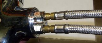
A typical sensor for installation on a pipeline requires a fitting with five terminals:
- water inlet and outlet;
- exit to expansion tank;
- under the pressure switch, usually with external thread;
- branch for pressure gauge.
A cord from the pump is connected to the sensor to control turning it on or off. The power supply is provided by a cable that is laid to the panel.
Installation recommendations
When placing a pressure sensor in the line, the following recommendations must be observed:
- For the device to work correctly, the temperature range in which it is operated should not exceed -4 - +40 C.
- The automation is placed not only indoors, but also in a caisson well; after the pump, fine and deep water filters should be installed in the line - this will prevent the fitting with the membrane from clogging with dirt, which can lead to incorrect operation of the device.
- Many devices are designed to work only with cold water; during operation, its temperature should not exceed permissible limits, for example, no more than +55 C. for RD models.
- The power of the electric pump connected through the device should not exceed the values specified in the passport data - violation of this rule can lead to sticking of the contacts and failure of the relay.
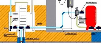
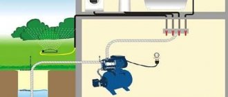
Rice. 11 Example of placement of a hydraulic relay with a deep-well electric pump
A pressure sensor or switch is the main device for ensuring the automatic operation of water intake equipment; it is part of any electric pumping station or water supply system with a deep-well electric pump. Its installation and adjustment does not present any particular difficulties even for an unprepared homeowner, and compliance with the basic rules of placement and installation will ensure uninterrupted operation of the device for ten years.
How to setup?
The factory settings of the sensor are often left unchanged , but if necessary, the upper or lower limits of the range are adjusted to suit your needs. First, they test the system, record existing parameters and make adjustments.
In the water supply system
The pressure value is changed by tightening or loosening the springs:
the large one is responsible for the lower point, which turns on the pump;- set the required pressure on the pressure gauge and tighten the spring until the water intake motor starts working;
- the upper limit is changed with a small spring, then the system is tested, the actual values are checked.
In simple sensors, the housing cover is removed to access the regulators; in advanced modifications, there are external screws or buttons for adjustment.
In frequency converter
When connected via a frequency converter, changing the settings leads to a decrease or increase in the signal supplied to the converter.
A convenient mode is when the pump activation is set to approximately 1 atm. below the standard value. This difference will allow you to accumulate up to 10 liters of water in the accumulator and not turn on the pump every time you need to rinse your hands or draw a mug of water.
When it's time to take a shower, the pumping station will turn on and maintain constant pressure without a noticeable difference.
The video will show you how to adjust the pressure sensor at the pumping station:
Principles of adjustment
A device that monitors pressure and controls the operation of the pump automatically is very convenient to use. It requires almost no attention or maintenance. Perhaps 1-2 times a year you have to clean it of debris and check how the sensor copes with controlling the given range of water pressure.
What do you need to know before starting work?
Initially, the owner who purchased such a device has 2 options:
- leave the settings set at the factory;
- independently set the desired response range.
The first option is convenient when the parameters of the pump and pressure in the system correspond to the factory settings. For simple domestic models they are 1.4 and 2.8 atmospheres, respectively, for the lower and upper limits. Depending on the device and the manufacturer, these figures may differ.
The upper and lower limits of the factory settings must be indicated in the passport in the technical characteristics section
If the specified range suits the home owner, then all that remains is to install the sensor, following the installation instructions. Otherwise, you will have to independently adjust the sensor that controls the water pressure in a private water supply system.
It is more convenient to adjust the desired range in models that have a built-in pressure gauge and a more sensitive graduation scale. But the cost of such a solution will cost a tidy sum.
Before you start adjusting the device, you need to look at the maximum permissible operating range in the passport and compare this data with the power of the pump. It is important to leave a small reserve - you cannot allow the equipment to work to its maximum. This gap is about 0.5 atmospheres.
Also, it should be remembered that the optimal operating range of the pump is 1-1.5 atm. There is no point in doing more - water hammer may occur, causing irreparable damage to the equipment. The minimum threshold for turning on the pump must be at least 1.4 atm.
If during pump operation there is a possibility that the water level in the water intake will drop below the limits required for normal operation of the equipment, then it is better to supplement the pressure sensor with an automation unit. Then the unit will turn off when there is a threat of “dry running”
Even before setting up the sensor, you must find out what pressure is in the accumulator. To do this, disconnect it from the network, drain the water, and check the pressure with a pressure gauge.
If the reading is 1.4 atmospheres or less, then you need to pump it up to 1.5 atm. Otherwise, excess air should be released to this value by pressing the nipple.
Step-by-step pressure sensor setup
Depending on the sensor model, the steps to adjust it will vary slightly. Each device has its own parts that are responsible for setting the operating range of the pump. For example, the German FF4-8 has a division scale where everything is extremely easy to adjust. And you don’t need to remove the cover to make adjustments - it’s transparent.
You can make the adjustment yourself by studying the device data sheet or invite a specialist
If this is a complex electronic pressure controller with additional functions, then you should carefully read the specifications in the passport for indicating the operating pressure for the system. Moreover, it should be at least 0.5 atm less than the maximum permissible values.
Regardless of the brand and model of the device that monitors pressure, you must first check the lower limit at which the pump operates. To do this, you need to drain the water by opening the tap. As soon as water pumping begins, you need to record the pressure gauge readings.
Some sensor models have a built-in pressure gauge, others do not, for which you need to buy a separate measuring device
When the pump turns off, this value should also be recorded - this is the upper limit of the maximum permissible pressure in the system. Moreover, these readings should not differ from each other by more than 1.5 atmospheres.
Knowing the initial response range of the equipment, all that remains is to adjust the upper limit and its difference with the lower one. If this is a model with two springs, then adjustment will be made using a wrench.
First you have to remove the protective cover to see 2 springs underneath. The large one is responsible for changing the upper limit of the limit. To decrease or increase the limit value, you have to turn the nut. Moreover, it is better to do this slowly, turning it 0.5 - 1 turn.
Having tightened it once, you need to open the tap and check the pressure value obtained on the pressure gauge to turn on the pump. If the indicator is not satisfactory, continue turning the nut.
Sometimes, instead of adjustment, it is necessary to clean the flange and contacts of the device from mineral deposits. Inclusions are brought by water that has undergone insufficient purification or transported through old metal pipes
A small spring is responsible for changing the difference between the upper and lower pressure. When tightening it, it is important to remember that this difference should not be more than 1.5 atm. When the nut in front of the large spring is tightened, and the small nut is also adjusted, you should open the tap again and start draining the water.
As soon as the pump turns on, you need to remember the value indicated by the pressure gauge - this will be the lower limit. After this, you have to wait for the pressure in the system to increase. As soon as it reaches the upper limit, the pump will turn off. This reading also needs to be remembered and compared with the lower one.
If the numbers differ by 1.5-1 atm and do not intersect with the minimum and maximum permissible operating values, then everything was successful. Otherwise, you need to drain the water again and start the adjustment again.
Possible breakdowns and ways to solve them
If the pumping station malfunctions, general diagnostics are carried out to prevent pump failure or damage to the tank membrane.
Automation can cause a malfunction in the following cases:
Weak or excessive pressure occurs when the setting is incorrect; readjustment is carried out.- Loosening of the screws holding the contact group leads to spontaneous switching on or off of the device, heating and even burning of the contacts; to eliminate this, replace the unit.
- If a pipeline or fitting is clogged, the device reacts with a delay; it is corrected by cleaning the system, and to prevent it, install reliable filters between the pump and the sensor.
Before carrying out maintenance work, turn off the power supply and do not carry out any actions while the pump is running.
The device will not work correctly if it is placed at a large distance from the accumulator or has a narrowed connection to the tank. In this case, it is easier to redo the equipment connection diagram.
The video will show you how to clean the water pressure sensor:
Popular controller models
Equipment and spare parts for the plumbing system are presented in specialized stores in a fairly wide range. As for pressure sensors, these can be Russian-made models that have a low cost, as well as imported expensive multifunctional products. It is important to understand that expensive models of pressure sensors are capable of not only monitoring water pressure, but can equalize its values.
Regardless of cost, all pressure sensors are divided into two groups:
- Electromechanical devices are characterized by the presence of a metal plate. When the pressure in the hydraulic tank increases or decreases, the membrane has a corresponding effect on the plate, which as a result closes or opens the contacts. If there is insufficient pressure, the pump turns on, and vice versa, high pressure causes the pump to turn off.
- Electronic sensors also respond to membrane pressure, but in this case the signal goes to the automatic control system. After processing the information, a command is received to turn the pump on or off. The advantage of such equipment is the reaction to the slightest deviations from the established indicators and the presence of protection against “dry” running. In addition, electronic sensors can signal problems in the system or its emergency shutdown in the form of a message to a mobile device.
If we consider the most popular models of water pressure sensor, we can distinguish several options that occupy a niche of primacy:
- Pressure regulator KIT 02 from the Spanish manufacturer ESPA. The device is characterized by performing the functions of a pressure sensor with support for constant set parameters, the presence of protection against “dry” running, a reverse valve and a built-in pressure gauge. Capable of absorbing water hammer.
- Russian sensor RDM-5 from the company Dzhileks. One of the budget options with factory settings for the upper (2.8 atmospheres) and lower (1.4 atmospheres) limit values. The range can be changed by the owner within 1-4.6 atmospheres, which allows the operating values of the device to be made.
- Pressure sensor FF4-4 from the German company Grundfos. The device is characterized by an operating range of 0.07-4 atmospheres, which allows you to make settings with an accuracy of 0.01 atmospheres. For greater convenience, the water pressure transducer is equipped with a special scale and a transparent cover, which is especially important when making independent adjustments. The result is immediately visible on the scale, so there is no need to turn the nuts at random. The functionality of the pressure sensor and its attractive appearance ensures high demand for such models.
If we consider the area of use, we can say that complex electronic devices are best installed in private country houses where a family of several people is planned to live permanently.